Defining Anisotropic Tensors
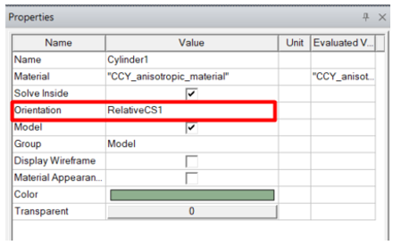
If a material property is anisotropic, its characteristics are defined by its anisotropy tensor. Each diagonal represents a tensor of your model along an axis. These tensors are relative to the coordinate system specified as the object’s Orientation property (when supported). Otherwise, the tensors conform to the global Cartesian coordinate system. By specifying different orientations, several objects can share the same anisotropic material but be oriented differently. Spherical and Cylindrical tensors must be converted to Cartesian coordinates, as described below. In such cases you must specify the coordinate system carefully.
Assigning Anisotropic Tensors
To assign anisotropic tensors to
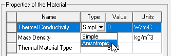
- From the View/Edit Material window, use the Type drop-down menu to select Anisotropic.
Three rows, labeled T(1,1), T(2,2), and T(3,3) appear, as shown below.
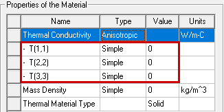
(The preceding images are based on the Thermal solution type.)
- For each of the new anisotropic property rows, use the Type drop-down menu to select either Simple or Nonlinear (when supported). This setting determines the type of Value you can enter.
- In the Value field, enter the
- For Young's Modulus – Enter the modulus along the direction of each tensor axis. Tensors T(1,1), T(2,2), and T(3,3) correspond to the global Cartesian X, Y, and Z axes, respectively.
- For Poisson's Ratio – This property quantifies how a strain in one direction produces a strain along an axis 90 degrees from the first axis. Enter the ratio for each axis pair. Tensors T(1,2), T(1,3), and T(2,3) correspond to the global Cartesian axis pairs XY, XZ, and YZ, respectively.
- For Thermal Conductivity – Enter the thermal conductivity along the direction of each tensor axis. Tensors T(1,1), T(2,2), and T(3,3) correspond to the global Cartesian X, Y, and Z axes, respectively.
- Click OK to save the values and return to the Select Definition window.
Cylindrical Anisotropic Material Properties: Tensor Conversion from Cylindrical to Cartesian CS
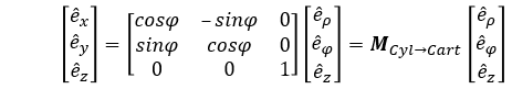
where M is a transformation matrix.
Tensors, describing material properties, could be transformed accordingly as
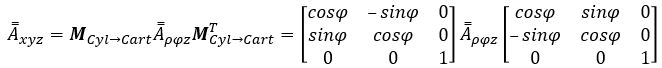
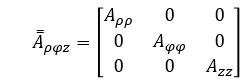
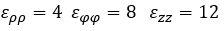
If we assume only the diagonal components as non-zeros for the tensor in the Cylindrical basis
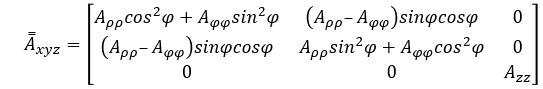
the resulting tensor in the Cartesian basis could be derived as
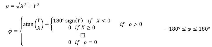
We should define and using X, Y and Z:
Related
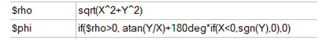
First you create all required Project variables.
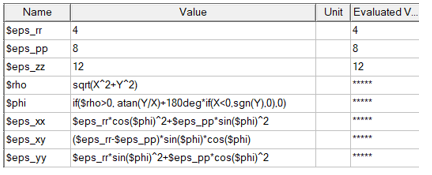
You can then use the variables to create the material.
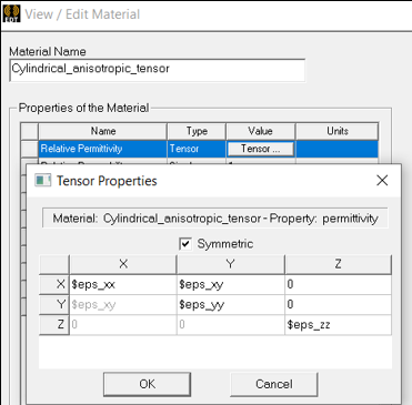
For the test case for cylindrical anisotropic material definition, using converted tensors based on variables:
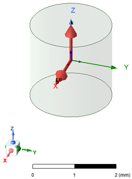
For this problem type, consider that scattering on a cylinder where diameter and height are equal to 0.2 wavelength and a plane wave excitation along Z-axis.
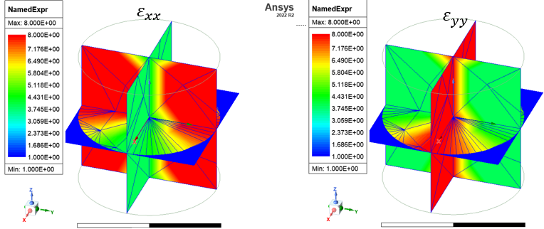
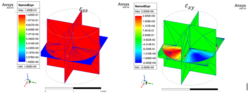
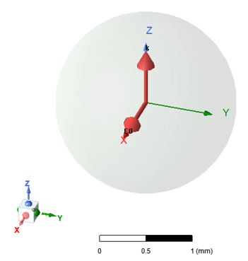
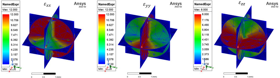
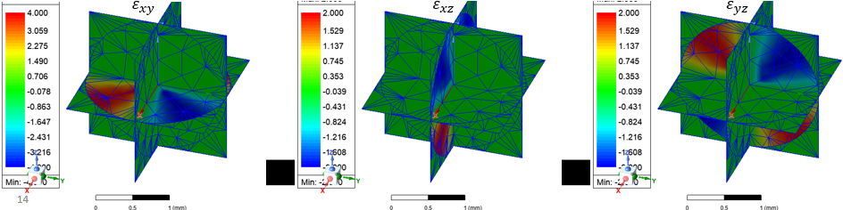
Spherical Anisotropic Material Properties: Tensor Conversion from Spherical to Cartesian CS
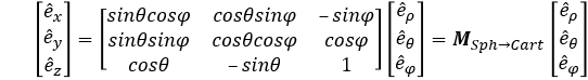
where M is a transformation matrix
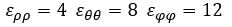
Tensors, describing material properties, could be transformed accordingly as

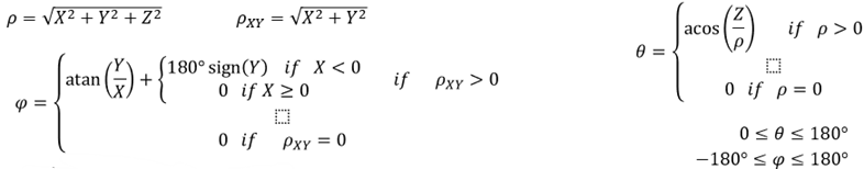
We should define ρ,θ , and φ using X, Y and Z
Related
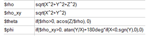
Note: the material characteristics close to the Z-axis could be slightly incorrect because of uncertainty of φ in the case of ρxy=0.
First you must create the necessary project variables.
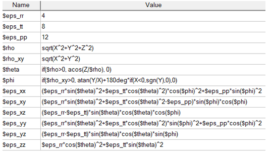
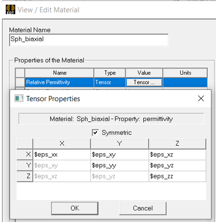
You can then use the variables to create the material.
For the test case:
Problem type: scattering on a sphere(diameter is equal to 0.2 wavelength).
Plane wave excitation along Z-axis