Displacement
A Displacement excitation has two purposes:
- Displace an entity a specified distance in a specified direction.
- Prevent motion (that is, constrain an entity) in one or more particular directions while allowing motion in the other directions. See the topic, Example: Displacements as Directional Supports, for a typical application.
Often, a displacement excitation is used to achieve a combination of these two purposes. For example, you might want to displace an edge or face a certain distance in the X direction (non-zero X Displacement), prevent motion in the Y direction (Y Displacement = 0), and allow the Z displacement that will occur naturally due to motion or deformation of the structure (Z direction = "Free"). You can achieve all three of these goals by assigning a single displacement excitation.
You can assign Displacement excitations to the following entity types:
- Faces of solid objects
- Edges of solid objects
- Vertices of solid objects: (beta feature for Structural solutions only)
Faces or edges to which you assign a Displacement may be of any shape or orientation, flat/straight or curved.
How to Assign a Displacement Excitation:
The appearance of the Displacement dialog box varies depending on whether the selection set includes an edge and whether the Normal To or Component option is selected (when applicable). The following procedure covers all possible variants:
- Using the Face, Edge, or Multi selection mode, select one or more solid object faces and/or edges.
- Use one of the following three methods of accessing the Displacement dialog box:
- Right-click in the Modeler window and choose Assign Excitation > Displacement from the shortcut menu.
- Right-click Excitations in the Project Manager and choose Assign > Displacement.
- From the menu bar, click Mechanical > Excitations > Assign > Displacement.
- Optionally, change the Name of the excitation. (The default name is Displacementx, where x is a number incremented for each displacement you add.)
- If your selection set includes only faces, choose one of the following two options from the Define By drop-down menu:
- Normal To: Displacement acts in the face-normal direction
- A positive displacement pulls outward on the face, away from the solid body.
- A negative displacement pushes inward on the face, towards the solid body.
- Component: Specify X, Y, and Z components of displacement (global and user-defined coordinate systems are supported)
- Specify the displacement as follows, depending on the type of selected entities and your selection in the previous step:
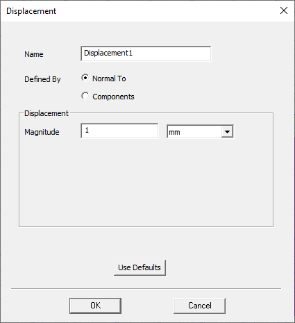
- If you selected the Normal To option (faces only), the dialog box appearance will be as shown in the following figure:
- Specify the desired displacement Magniutde.
- Choose the length units from the adjacent drop-down menu.
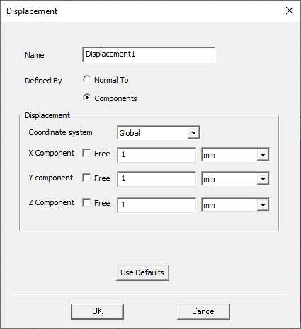
- If you selected the Components option (faces only), the dialog box appearance will be as shown in the following figure:
- From the Coordinate System drop-down menu, choose the CS on which the displacement components will be based.
- Optionally, for any direction in which you do NOT want to impose a displacement but want to leave the selected entities free to displace on their own, select the Free checkbox.
- For non-Free directions, type the displacement component magnitudes in the X Component, Y Component, and Z Component text boxes.
- Choose the length units for each applicable component from the adjacent drop-down menu. For zero-components, the units choice doesn't matter.
- Click OK.
The Normal To option is not supported for displacements assigned to edges or vertices.
For this option:
For a curved face, the normal direction varies and is separately evaluated at each node along the face, since both displacement excitations and resultant displacements are computed at nodes.
Or, if your selection set included at least one edge, the dialog box appearance will be as shown in the following figure:
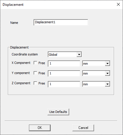
In either case, do as follows:
The menu will list the Global CS and any user-defined CSs that exist in the design. Global is selected by default.
Select one, two, or none of the Free checkboxes. If you select all three, the displacement excitation will have no effect on the model.
The values may be zero (to prevent motion), positive, or negative.
The displacement appears under Excitations in the Project Manager: