Example: Displacements as Directional Supports
Displacement excitations can produce controlled movement of an object or assembly along a specified direction (for example, to represent the action of a hydraulic cylinder or linear actuator). You can also use them to deform a structure, to determine the stress when it is displaced a specific distance, but the load required to do so is unknown.
Another popular usage of displacements is to provide constraints in specific directions while allowing motion in other directions. Achieve this effect by selecting the Free option for the directions along which you want the object to move without restriction. Clear the Free option and specify a zero displacement for the direction or directions in which you wish to prevent motion. This technique is particularly useful for thermal stress analyses, where conventional supports over-constrain a model and produce inaccurate stress and displacement results.
In this example, we present a typical three-point directional support scheme. It's purpose is to provide a statically stable analysis model while not impeding the thermal expansion or contraction of the geometry that occurs when the temperature changes. That is, no rigid body translation or rotation is permitted, but the model is free to change size and shape.
The Problem with Conventional Fixed supports:
Any edge or face that is fixed is prevented from expanding, contracting, or bending as the material is heated or cooled. The result is exaggeration of thermal stresses along the constrained entities and underestimation of the model displacement.
The Solution:
Three points that are not collinear define a plane. Choose three model vertices that lie on a plane that is parallel to a global plane or a plane of a user-defined coordinate system. Assign a fixed support to one of the three vertices, constrain two degrees of freedom (DOF) of another one, and constrain only one DOF of the third vertex. The directions are not arbitrary, but the example that follows demonstrates the proper configuration.
Solid finite elements possess three DOF: X-, Y-, and Z-translation. They do not have rotational DOF and therefore cannot support torsional loads or rotational constraints at their nodes. Simply stated, if you fully fixed a single vertex of a model, it would behave as if that vertex were a frictionless ball joint. The point could not translate, but the model would swivel in any direction about that point, and it would be statically unstable. Similarly, if two points were fully fixed, the model would be free to rotate about the line connecting the two points, behaving like a frictionless hinge. A third, non-collinear point is required to prevent that rotation.
Consider the following simple model of a bimetallic strip. When heated, the top strip will expand more than the bottom one due to the difference between the thermal expansion coefficients of the two materials.
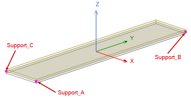
The selected vertices are at the corners of the inside faces where the dissimilar metals meet. This decision was arbitrary. You could also use the corners of the top or bottom face of the model, as long as all three points lie on a plane that is parallel to a coordinate system plane (XY in this case). Support details follow:
- Support_A: Fixed Support (X, Y, and Z translation constrained)
- Support_B: Displacement (X and Z = 0 mm, Y = Free)
- Support_C: Displacement (X and Y = Free, Z = 0 mm)
This support prevents X-rotation and Z-rotation of the model about Support_A but allows translation in the Y direction.
This support prevents Y-rotation of the model about Support_A and Support_B but allows translation in the X and Y directions.
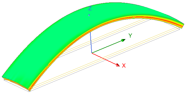
Notice the displaced shape of the model when heated. In the following Displacement Magnitude overlay
The observed complete freedom of thermal expansion could not be achieved with fixed supports assigned to any face, to any two non-collinear edges, or to three non-collinear vertices.
Additionally, in the following Equivalent Stress overlay, notice that there is no stress exaggeration at the three support vertices: