
Replacing or Editing Layout Components
Use the Replace Component command to edit the properties that were specified when a layout component was inserted into your design or to replace the component with a different one. This command is located in the shortcut menu that appears when you right-click a layout component entry in the Project Manager tree's 3D Components folder. A multi-tab window appears, Edit Layout Component, which is very similar to the Insert Layout Component window discussed in Adding a Layout Component except for the following differences:
-
None of the tabs have the Target Coordinate System parameter. If you would like to change the placement of a layout component, see Edit Placement of a Layout Component.
- The General tab of the Edit Layout Component window includes a Definition drop-down menu for selecting an AEDB folder, *.aedbcomp file, or existing component definition in the current design. Use this drop-down menu to replace the current component with a different one.
- In the Variable Mapping tab of the Edit Layout Component window, you cannot revert previously mapped instance parameter variables to the original numeric values as you can in the Insert Layout Component window. Once the mapping is committed by completing the insertion process, the variables remain as instance parameters.
- The Parameters tab of the Edit Layout Component window does not include an option to make local design or project variables from component instance parameters. You can only create local design or project variables when originally adding the layout component to your design. Even if you have chosen to map additional source layout variables to instance parameter variables when editing a component, you cannot automatically create associated local design or project variables from the Edit Layout Component window.
- The tab locations differ between the two windows. For Insert Layout Component, the tabs are located near the bottom of the window. For Edit Layout Component, the tabs are located near the top of the window. However, the same tabs are included in both windows, and they appear in the same order.
Edit/Replace Procedure
To edit an existing layout component in your
- Under 3D Components in the Project Manager, right click the <Layout_Component_Name> and choose Replace Component.
- Optionally, to select a different component to replace the current one, choose one of the following three options from the Definition drop-down menu:
- Import .aedbcomp File: Choose this option if you have exported an HFSS 3D Layout as a single-file Layout Component (*.aedbcomp)
- Browse to Project .aedb Folder: Choose this option to specify the location of an Ansys electronics database folder (*.aedb) to use in the creation of the layout component. This folder is where HFSS 3D Layout design filesets are stored.
- Double-click the folder to open it and continue drilling down through Layout Components\<Design_Name>\<Design_Name>.aedb until a single Stride folder is the only thing contained in the selected folder. Then click Open.
- Layout component definitions that have previously been added to the current project will also be listed in the Definition drop-down menu. You can choose an alternative component, if any exist, to replace the one being edited.
- Progress through the Variable Mapping, Coordinate System, and Parameters tabs of the Edit Layout Component window in the same manner as detailed in the Adding a Layout Component topic. Take into account the limitations described above.
- Click OK when you are done editing the layout component.
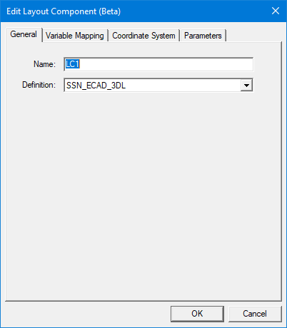
The Edit Layout Component window appears with the General tab initially selected:
A Select layout component file to import dialog box appears in which you can browse to the file location and select and open it.
The layout may contain multiple designs. In the "Select layout component folder to import" dialog box that appears. Browse to the desired *.aedb folder as follows:
If you selected a new source file or folder for the layout component, a new layout component is added under Definitions > Components in the Project Manager. Additionally, the layout component in the Modeler window is regenerated.
If the component's visualization options were customized in the design, they will be reset to their default configuration whenever the layout component is replaced or regenerated after editing. When this occurs, repeat step 8 in the Adding a Layout Component procedure to restore your preferred visualization options.