Assigning a Thin Layer (Air Gap) Boundary for a Magnetic Solver
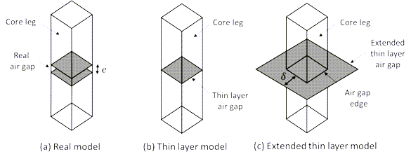
When two parts of the domain are separated by a thin volume representing an air gap, it can be modeled using a Thin Layer boundary condition. This boundary creates a scalar potential discontinuity across the two sides of the surface based on its thickness. When the Air Gap option is selected, the relative magnetic permeability is assumed to be equal to one. The thin layer is defined purely in terms of its thickness in this case.
This boundary condition can be used to model thin ferromagnetic structures such as shields and narrow air gaps in power transformers, inductors, or any other electric device without needing to explicitly model (and mesh) the thin volume.
- The conductivity of the thin layer in the magnetostatic solution is assumed to be zero. This is a valid assumption as no currents flow inside the thin layer, which is guaranteed by the thin layer not touching conductors and by the fact that the magnetostatic solution cannot represent induced current effects. For the induced current analysis, the AC Magnetic solution is recommended.
- The thin layer cannot be a closed shell encompassing a conductor.
- The thin layer does not support a mechanical movement, i.e., the boundary condition cannot be applied to the interface of moving and stationary bodies.
- The thin layer cannot be defined on a conductor boundary or as a sheet object that touches or crosses any conducting body. In such cases, the Maxwell solver displays an error message indicating the name of the conducting body that the thin layer is touching.
For the 3D Magnetostatic solver, the thin layer is defined in terms of its thickness and magnetic permeability.
To define a thin layer boundary:
-
Select the section of the geometry on which you want to apply the boundary condition (typically a sheet object or face of a 3D body).
-
Click Maxwell 3D > Boundaries > Assign > Thin Layer to open the Thin Layer window.
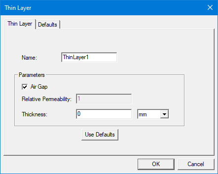
- Enter a name for the boundary in the Name box, or accept the default.
- If an air gap is being modeled, keep the Air Gap option checked. The Relative Permeability field will be grayed out (non-editable) and set to 1.
- If Air Gap is checked, enter the Thickness of the air gap and the unit of measure. It must be a value greater than zero. The use of a variable is supported, but it cannot be an intrinsic variable.
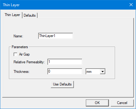
- If the Air Gap is unchecked, the thin layer can represent a thin ferromagnet. In this case, enter the thickness of the layer and the material's Relative Permeability in the respective fields. The use of a variable is supported, but it cannot be an intrinsic variable.
- Optionally, click Use Defaults to revert to the default values, which are defined in the Defaults tab.
- Click OK to assign the boundary to the selected object.
From the Defaults tab, the Save Defaults button saves the values currently defined on the Thin Layer tab as the defaults to be assigned to new impedance boundaries. Revert to Standard Defaults clears existing user-defined values and replaces them with the standard default values.
The Project Manager tree lists the newly assigned thin layer boundary in the tree. You can select the boundary in the tree to view and edit its thickness in the Properties window. You can also double-click the boundary entry in the tree to open it for editing in the Thin Layer window.
Getting Better Convergence with the Thin Layer Model
For a magnetostatic simulation, the thin layer model for air gaps requires the duplication of the scalar potential to create a field discontinuity beyond the dimension of the sheet object and correctly represent the fringing flux effects. The Maxwell solver automatically duplicates the potential in one layer of elements from the gap edges. However, during the mesh adaptive process, the lateral elements may become too small and thus too close to the gap sides. This results in a low convergence of the mesh adaptive steps as the magnetic energy on such elements becomes more important. To improve convergence, the user can extend the sheet object manually (see figure below). Better convergence is observed by raising its lateral sides from one to three times the air gap thickness (δ≅3e) depending on the model geometry.