
Radiated Fields
When HFSS calculates radiation fields, the values of the fields over the radiation surface are used to compute the fields in the space surrounding the device. This space is typically split into two regions — the near-field region and the far-field region. The near-field region is the region closest to the source. In general, the electric field E(x,y,z) external to the region bounded by a closed surface may be written as
|
|

|
(1) |
where
- s represents the radiation boundary surfaces.
- j is the imaginary unit,
 .
.
- w is the angular frequency, 2pf.
- m0 is the relative permeability of the free space, 4p´10-7 Wb/Am.
- Htan is the component of the magnetic field that is tangential to the surface.
- Enormal is the component of the electric field that is normal to the surface.
- Etan is the component of the electric field that is tangential to the surface.
- G is the free space Green's function, given by
|
|
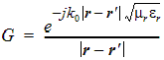
|
(2) |
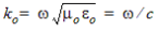
- k0 is the free space wave number,
- rand
 represent field
points and source points on the surface, respectively.
represent field
points and source points on the surface, respectively.
- e0 is the permittivity of free space, 1/(c2m0)
- er is the relative permittivity of a dielectric.
- mr is the relative permeability of a dielectric.
This r dependence is characteristic of a spherical wave, a key feature of far fields. The far field is a spherical TEM wave with the following equation:
|
|
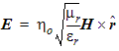
|
(3) |
where h0 is the intrinsic impedance of free
space,  .
.
You can select the material in which the objects are embedded (the default is vacuum). In that case, the Green's function and the intrinsic impedance of that material will be used, so the far field will be correct. See Global Material Environment.
When calculating the near fields, HFSS uses the general expressions given in (eq. 1). You must specify the radial coordinate r. Because it can be used to compute fields at an arbitrary radius from the radiating structure, this command can be useful in EMC applications.
If HFSS calculates the near fields in a problem containing an incident wave, the radius at which the fields are calculated is very important. If the radius is within the solution region, then the fields calculated are either the total fields or the scattered fields depending upon which is selected. If the radius is outside the solution region, then the fields calculated are only the scattered fields.
When calculating the far fields, the previously discussed far-field approximations are used, and the result is valid only for field points in the far-field region.
A radiation or PML boundary or Floquet port must have been defined in the design for HFSS to calculate radiated fields.