
Link as Composite Port
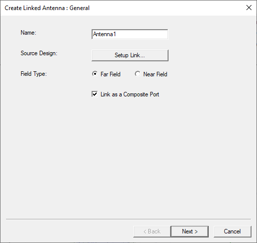
HFSS lets you create a one-way link from a Driven Modal design or a Driven Terminal design with a single terminal to an SBR+ design, as discussed in detail here. The source can be a finite array design, including designs with blockages. The Link as Composite Port option in the Setup Link dialog addresses the situation where an imported design contains many ports.
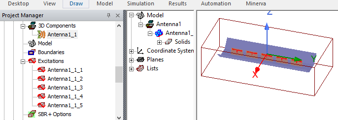
By default, the model window displays the same number of virtual ports in the SBR+ target design. However, if the source design contains many virtual ports, they will look cluttered and require significant computational resources to solve. For example, if you used the planar flared dipole array array example as a linked antenna, the excitations in the SBR+ target design shows this.
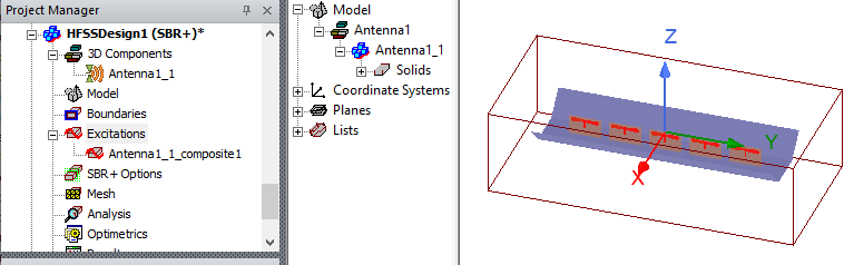
By checking Link as a Composite Port, you create a single composite port in the SBR+ target design to represent all the ports in the HFSS source design. During computation, the SBR+ target design sends the information about a single composite port to the solver, rather than information about all the ports. This saves a significant amount of resources.
A composite port requires a single phase center, whereas each regular port requires its own phase center.
In order to reduce the N original ports of the source design to a single port in the target SBR+ design, Link As Composite Port implicitly (mathematically, not physically) incorporates a 1-to-N feed network that provides a perfect match to the linked multi-port antenna. At the same time, the composite-port link is formulated in such a way that some antenna pattern metrics and results, such as peak realized gain and radiated near- and far-fields, remain consistent between equivalent composite and regularly linked antenna configurations. As a result, when linking an antenna as a composite port into an SBR+ design, whether as a near-field or far-field link, you should expect the following results and behaviors:
- Self-coupling: Sii = 0 due to the matched network assumption.
- Cross-coupling: magnitude of Sji will be larger when one or both of the referenced ports (j,i) are compositely linked than in the case of a regular link due to the matched network assumption.
- Accepted power: the accepted power reported in the Antenna Parameters table can be significantly different, especially if the magnitudes of Sji are large in the case of composite port link(s), due to the definition of accepted power including the effects of cross-coupling in determining the amount of incident power returned to each port in the target design. This effect can be verified (by eliminating it) by disabling SBR+ couplings in the Select Tx/Rx Antennas dialog.
- (Peak) Gain: the reported gain and peak gain can be significantly different owing to the inverse relationship of regular gain and accepted power (see above)
- (Peak) Realized Gain and Max U: these reported antenna parameters will match between composite and regular link configurations owing to the design and formulation of the Link as Composite Port feature.