
IBIS I/O Wizard Power/Ground Pin Setup
To configure Power and Ground settings, click Set as power/ground pins in the I/O Wizard window; this opens the Power/Ground Setup window for the selected pins.
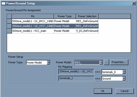
Fields in the main grid-display window are not editable, but instead show the status of what you configure using the PowerSetup fields at the bottom of the window. You can select multiple rows and click the Power Setup fields to make multiple changes to many pins simultaneously.
- PowerType can either be Buffer Connection, Reference Pin, or Power Model.
— Buffer Connection means the pin are directly connected to the Pull Up or Pull Down, according to what was specified in the Signal Setup window.
— Reference Pin does not specifically assign a Power source or Ground, but this setting can be used for pin mapping.
— Power Model allows a one or two port component to be connected directly to the pin. Click the [...] button to load a model. If the component selected for the Power Model has two pins, the Pin Mapping area is displayed. The top Pin Mapping area selects which of the Power Model’s terminals is directly connected to the Power Pin selected in the pin grid. The bottom Pin Mapping area allows you to assign the remaining Power Model terminal to a net.
- Clicking Properties allows you to customize the parameters for the selected Power Model component.
- In order to connect a ground terminal, select Power Type: Power Model, then click the [...] button to load a RES_ component as the Power Model. This two port component, when not configured with a resistance parameter, acts as a short. The pin mapping for the RES_ Power Component allows you to then short the Power pin to Ground.
Click OK to close the window and implement any changes that have been configured.