
Viewing DC Bias Values in a Schematic
To run a DC bias analysis on a circuit design in the Schematic Editor, select Twin Builder > View DC Bias Values. A submenu containing three items appears:
- Show DC Bias
- Update
- Display Options
Show DC Bias – Toggles visibility of existing data on and off. If there is no existing data, a simulation runs to create it. A check mark appears next to the menu command to indicate that visibility is turned on.
Update – Causes a simulation to run so the data reflects the current design topology and settings. Update is disabled if DC bias data is not visible.
Display Options – Opens the DC Display Options dialog box allowing display customization:
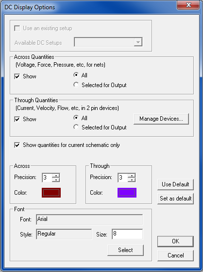
Use the Use an existing setup check box to pick an existing DC setup, listed in the Available DC Setups drop-down list. The check box and list are disabled if there are no existing DC setups. If an existing setup is not chosen, a temporary setup that uses default values is created when needed.
In the Across Quantities panel, toggle display of net “across” values with the Show check box. Select All to show a value for every conservative net. Select Selected for Output to display the net “across” quantities selected in the Output dialog box.
Similarly, in the Through Quantities panel, toggle display of component “through” values with the Show check box. Select All to show a value for every component instance. Select Selected for Output to display the component instance “through” quantities selected in the Output dialog box.
Click Manage Devices to choose appropriate 2-terminal devices through the following dialog box:
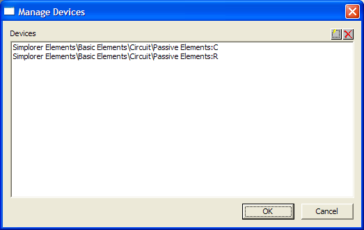
Click  to add devices to the list.
Select a device and click  to remove it from the list.
Select Show quantities for current schematic only to limit the bias display to the current schematic. If the box is cleared, bias values display for the current design and all its subdesigns. In a subdesign, display of bias values is based on a parent's simulation if the parent's check box was cleared and that bias display was most recently shown. To see values based on simulation of the current subdesign, invoke Twin Builder/View DC Bias Values/Update.
Use the Across and Through panels to control the precision (number of decimal points) and color used to display these values.
Use the Font panel to control the font used for the displayed values. Click Select to open the Font dialog box. Use the sliders to select the desired font, font style, and size, then click OK to return to the DC Display Options dialog box.
Click Use Default to restore the default option values in the dialog box. Click Set as default to make the current options the defaults.
Click OK to enable the specified options, or click Cancel to close the dialog box without changing any options.
Related Topics
Setting the Active Analysis Setup