
Example of a Worst Case Analysis
This example contains a simple voltage divider circuit illustrating worst case analysis (WCA).
The following schematic contains two resistors (R1 and R2) that divide voltage supply E1. The output of interest is VM1.V.
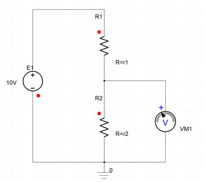
Simple Voltage Divider
The following information is available from the manufacturer:
| Nominal | Tolerance | |
| R1 | 5 ohm | +/- 20% |
| R2 | 5 ohm | +20% , -40% |
To determine the worst values of output VM1.V caused by uncertainty of the resistors, you want to find both the upper and lower bounds of VM1.V because either low or over voltage can cause problems.
In Twin Builder, to estimate the worst case based on the sensitivity analysis result:
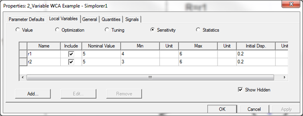
- Set the range of variables accordingly.
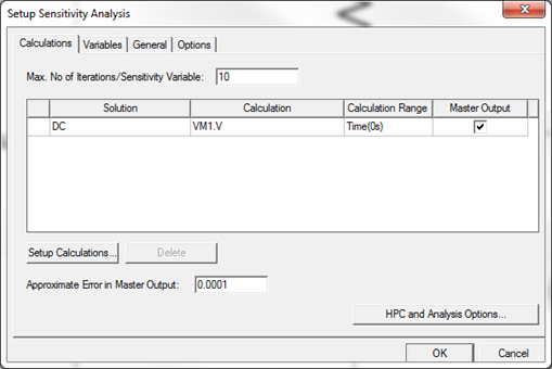
- Set up the sensitivity analysis of DC analysis of VM1.V.
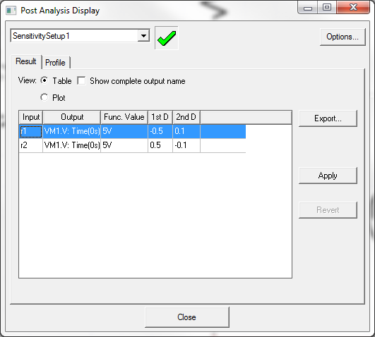
- Review the sensitivity analysis result. Note the first derivative is negative to r1 and positive to r2. Assuming the circuit is linear, which is true in this case, VM1.V is maximized (6V) with a minimal r1 and a maximal r2 (that is, r1=4 and r2=6), and minimized (3.3V) with r1=6 and r2=3.
This method can be generalized to multiple variables, and it requires two extra analyses, one for upper bound and one for lower bound, regardless of the number of variables. The following example shows the upper bound in variation 22.
