
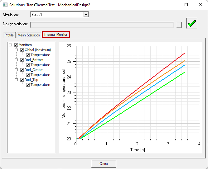
Thermal Monitor
Prior to solving a Transient Thermal analysis, you can assign points at which the temperature result will be monitored. After solving, you can plot the temperature versus time results for all user-assigned points. Additionally, the global maximum temperature versus time is plotted for all transient thermal solutions.
Points are defined by selecting vertices, a drawn point, linear edges, polyline objects, planar faces, planar objects, or solid objects. For each entity type, the monitor point is placed as follows:
- Vertices: The monitor points are located at each selected vertex.
- Drawn Points: Select drawn points in the History Tree rather than graphically. Monitor points are located at the coordinates of each selected point.
- Linear Edges: Monitor points are located at the midpoint of each selected linear (straight) edge. Curved edges are not supported.
- Multisegment Open Polyline Objects: Select multisegment polylines as objects or select them from the History Tree. Monitor points are located at the centroid of the combined set of line segments comprising each selected polyline object (see Note below).
- Planar Objects or Planar Faces: Monitor points are located at the centroid of each selected planar object or face (see Note below). Curved faces are not supported.
- Solid Objects: Monitor points are located at the centroid of each selected 3D object (see Note below).
For curved faces, faces with holes or cutouts, and hollow solids: The centroid may lay outside of the selected face or object. The point may also be outside of any model geometry, where no thermal result exists. Additionally, for multisegment polylines, there is a high probability that the centroid will not lie on one of the line segments.
Carefully verify the monitor point location in such cases. When you select a point under Monitor in the Project Manager, its coordinates appear in the docked Properties window. However, you cannot edit the coordinates. To correct a point, you either have to reassign it to a new selection or delete and recreate it.
Once monitor points have been assigned and the analysis solved, the plotted results appear in the Thermal Monitor tab of the Solutions dialog box. Access it from the Simulation ribbon tab (Solution Data command) or from the solution setup's shortcut menu (Thermal Monitor command).
To Assign Thermal Monitor Points
- From the Select drop-down menu on the Draw or Model ribbon tab, choose the desired selection mode (Object, Face, Edge, Vertex, or Multi).
- Click the desired entity whose centroid is where you want to monitor the thermal results.
- Access the Monitor Setup dialog box using one of the following three methods:
- From the menu bar, click Mechanical > Monitor > Assign > Point.
- Right-click in the Modeler window and choose Assign > Point from the shortcut menu.
- In the Project Manager, right-click Monitor and choose Assign > Point.
- Optionally, specify a custom Name for the monitor point.
- Click OK to assign the point and close the dialog box.
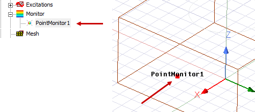
- Optionally, to visualize the monitor point, select it under Monitor in the Project Manager:
Alternatively, click in the Modeler window to make it active and press O, F, E, V, or M to choose the selection mode.
You can select multiple entities and assign thermal monitor points to each of them in a single operation, providing you do not wish to customize the names of each monitor point. If you wish to specify custom names, assign the monitor points one at a time.
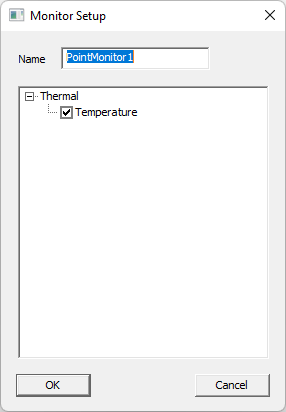
The default name is PointMonitorx, where "x" is an automatically incremented serial number.
To Display Thermal Monitor Results
After the monitor points have been assigned and the analysis has been started, access the plot of monitor results as follows. The monitor graph will be updated as the transient solution progresses. You need not wait until the solution is complete to observe the temperature:
- Access the Thermal Monitor tab of the Solutions dialog box using one of the following three methods:
- Under Analysis in the Project Manager, right click the <solution_setup_name> and choose Thermal Monitor from the shortcut menu.
- On the Results ribbon tab, click
 Solution Data. Then, select the Thermal Monitor tab.
 - From the menu bar, click Mechanical > Results > Solution Data. Then, click the Thermal Monitor tab.
- Optionally, click any checkbox to toggle the visibility of individual plot curves. The visibility options are useful for presenting single results or when two curves overlap, making the color ambiguous.
- Click Close when done.
You can choose to export thermal monitor results to CSV files at the completion of the analysis. See the Export Settings Tab section of the Design Settings for Mechanical topic.
Other Available Thermal Monitor Commands
The Monitor shortcut menu in the Project Manage, and the Monitor submenu within the Mechanical menu, provide the following additional commands:
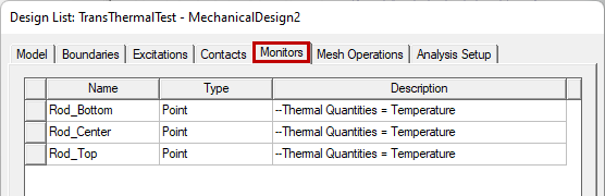
- List: Opens the Design Lists dialog box with the Monitors tab selected:
- Reassign: Execute this command after selecting an entity of the model to reassign an existing monitor point to a new point. The Reassign Monitor dialog box appears, in which you select the previously defined point to reassign. This command is also available when you right-click a point name under Monitor in the Project Manager, immediately reassigning the point that was right-clicked. In this case, the Reassign Monitor dialog box does not appear.
- Delete All: Delete all user-defined thermal monitor points.
- Visualization: Opens the Visualization Options dialog box:
- Set Default Base Name: Opens the Monitor Base Name dialog box:
This tab lists all user-defined thermal monitor points.
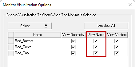
This dialog box is a common feature shared by Boundaries, Excitations, Contacts, Initial Temperature, and the thermal Monitor. In the context of thermal monitor points, only the View Name options are relevant. Vectors and Geometry (visualization overlays) are not applicable. Clear a View Name checkbox to prevent the name of a thermal monitor point from being displayed in the Modeler window when the point is selected in the Project Manager.
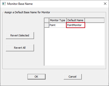
You can edit the default base name assigned to thermal monitor points in this dialog box.