
Design Settings for Mechanical
To set the design settings for Mechanical, use one of the following two methods:
- From the menu bar, click Mechanical > Design Settings. Or, right-click the active mechanical design in the Project Manager (MechanicalDesignx, by default) and choose Design Settings from the shortcut menu.
- Alternatively, select the name of the active mechanical design in the Project Manager (MechanicalDesignx, by default).
The Mechanical Design Settings dialog box appears with the Ambient Conditions tab initially selected.
|
Click each dot above to see all five dialog box tabs. |
")
")
")

")
The set of tabs that you see in the Design Settings dialog box is dependent of the currently active solution type, as detailed below.
The docked Properties window now includes a Mechanical tab, which contains a consolidated list of the settings from all of the Design Settings dialog box tabs:
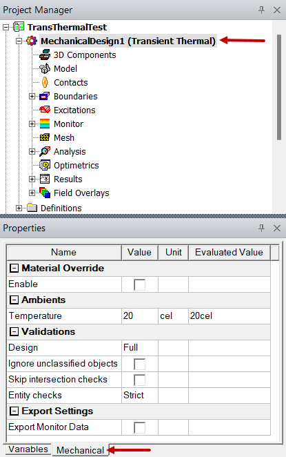
Ambient Conditions Tab
This tab, and the corresponding Ambients group in the Mechanical tab of the docked Properties window, is applicable only to Thermal solutions (steady-state or transient). The following setting is available:
- Temperature: This value is the default ambient temperature for Convection Boundaries, which can be overriden for individual boundaries by specifying an alternative temperature in the Convection dialog box.
Export Settings Tab
This tab, and the corresponding Export Settings group in the Mechanical tab of the docked Properties window, is applicable only to Transient Thermal solutions. It provides options to export thermal monitor results and to specify where to locate the exported data, as follows:
- Export monitor data after completing simulation: By default, thermal monitor results are not exported. Select this option to automatically export the monitor results after the simulation has finished. The result versus time data for each monitor point is exported in a comma-separated-values (CSV) text format.
- Override: By default, the monitor data is exported to the same folder as where the current project file is located. Select this option to enable the specification of an alternative export path. This option is unavailable unless the option Export monitor data after completing simulation is first selected.
- Path text box: By default, the path to the folder where the current project file is saved appears in this box and cannot be edited. To change the path for storing the exported data, you must first select the Override option (previous bullet).
- Ellipsis (...) button: When overriding the default export folder path, click this button to open the Choose Directory dialog box for browsing to the desired folder. This button is unavailable unless the first two options are both selected.
Set Material Override Tab
This tab, and the corresponding Material Override group in the docked Properties window, is only applicable to Thermal solutions (steady-state and transient). It contains a single setting that controls how objects are meshed and how materials are assigned in regions where objects overlap each other.
This option is only applicable when intersection checking is performed, and it has no effect when the Skip Intersection Checks option is selected.
- When Skip Intersection Checks is selected (under the Validations tab), the following will occur, regardless of the Enable material override state:
- When Enable material override is cleared (not selected):
- When Enable material override is selected:
- For cases where the geometry or material properties are such that the object to use in the region of overlap is ambiguous or cannot be resolved with a high level of confidence automatically, avoid the overlap. Instead, manually subtract the volume of intersection from the appropriate object to eliminate the intersection.
- Even in cases of ambiguous object overlap, the meshing routine will choose to subtract one of the objects from the other. In such cases, the Message Manager window reports the objects that are intersecting and the object material assigned in the overlap region. The automatic choice may not correctly represent the actual assembly that you intend. Carefully check such messages to ensure the proper material assignment in the overlapping regions.
Intersecting bodies will not cause the design solution to fail. At each intersection, the body with the smaller total volume will take precedence over the body with the larger total volume. The volume of the intersection region is not considered, only the full object volumes. Within the intersection region, the mesh and material properties will be dictated by the smaller object.
For the remaining conditions, the Skip Intersection Checks option is cleared.
The design will fail with an object intersection fatal error, both when performing a Validation in the user interface and during an attempt to solve the analysis.
The design will not fail in validation or during the solution. The body having a material with thermal conductivity above a fixed threshold (specifically 10 W/(m·°C) will take precedence in the region of intersection. If both objects are above this threshold, or if both are below the threshold, the body with the lower total volume takes takes precedence.
Validations Tab
This tab, and the corresponding group of settings in the Mechanical tab of the docked Properties window, provides options affecting model validation. These options control the extent of 3D model and Mechanical setup validations performed, and therefore the time involved. You can adjust the degree to which the software checks a model for faults that could degrade accuracy. The following options are available:
Model Options
The following settings affect only the "3D Model" stage of a design validation:
- Ignore Unclassified Objects: Generally, all objects in the 3D Modeler's History Tree are classified as solid, sheet, line, or point objects. However, in some cases, a drawing operation may produce null geometry, or it may fail and produce invalid geometry. For example, subtracting a tool object from an equal-volume or smaller blank object completely contained within the tool object would produce a null object. That is, the subtraction would completely remove the original blank object geometry. An example of a failed drawing operation is attempting to unite two solid objects when they only share an edge (not a portion of a face or volume). The union creates a non-manifold, invalid solid body. While not visible in the Modeler window, null and non-manifold objects are listed in the History Tree in an "Unclassified" branch.
- Skip Intersection Checks: This option, when selected, prevents detected object intersections (that is, overlapping volumes) from causing a fatal error and aborting the analysis solution. As this option also affects the behavior of material overrides, see the Set Material Override Tab section on this page.
- Entity Check Level: There are four levels of model validation that you can specify:
- None: Disables model validation. Use this option only for a known good model (for example, when you are solving variations of a previously validated model and wish to reduce the solution time).
- Warning Only: Allows all models to pass 3D Model validation regardless of any faults that are found. These faults are posted in the Message Manager window as warnings. However, whenever possible, it is best to repair model errors to ensure the accuracy of solution results.
- Basic: Allows a greater tolerance for model errors. As a result, many models will pass basic 3D Model validation. Significant faults are still flagged as model errors, thereby prohibiting the design from proceeding to the meshing stage of the analysis. Correct such errors before attempting to analyze the design. Alternatively, you could reduce the entity check level to Warning Only but at the risk of questionable results accuracy.
- Strict: This option is the defaul setting. It enforces a tighter tolerance for model faults than the Warning Only or Basic setting. All model faults found during 3D Model validation are posted in the Message Manager window. Correct these errors before attempting to analyze the design using the Strict setting. Alternatively, you could reduce the entity check level to Basic or Warning Only, with the understanding that the solution accuracy might be affected.
It is usually best to leave this global modeler validation option cleared so that unclassified objects are not ignored but are flagged as errors.
Mechanical Options
The following additional validation options appear in this section:
- Perform full validations: All design validations are performed.
- Perform minimal validations: All design validations are performed except for boundary and excitation overlaps.
In the Mechanical Design Settings dialog box (but not the docked Properties window), you have the option of saving the specified settings under any tab as the default for future projects. Do so by selecting Save As Default in one or more tabs.
Environment Conditions Tab
This tab, and the corresponding Environment group in the Mechanical tab of the docked Properties window, is applicable only to Structural solutions. The following setting is available:
- Temperature: This input sets the value of the global EnvTemp variable. It is the temperature at which the objects comprising the model are assumed to be in a stress-free and strain-free state. Temperatures assigned in, or imported into, the structural solution are interpreted relative to the EnvTemp value. The relative temperatures are use to determine thermal expansion or contraction and the resulting deformation and stresses. See Specifying the Reference Temperature for more information.