
Thermal Condition
This excitation is applicable only to the following entity type:
- Solid Objects
A Thermal Condition assigns a temperature to a body and can be one of the following two types:
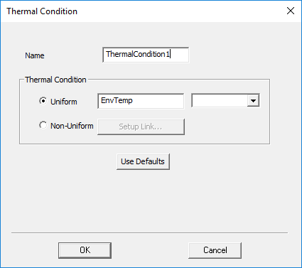
- Uniform: A user-defined temperature that is constant throughout the selected objects. You can specify the value numerically, in degrees Celsius (cel), Kelvin (kel, mkel, ckel, dkel), Fahrenheit (fah), or Rankine (rank). You can also select the EnvTemp variable, which is the default condition. The EnvTemp value is specified by the Temperature value in the Environment Conditions tab of the Mechanical Design Settings dialog box. This value is the temperature at which all objects are in a stress-free condition. Additionally, you can specify a user-defined design or project variable name for the uniform temperature, or you can enter an expression based on constants and variables.
- Non-Uniform: A temperature distribution imported from the results of a Mechanical–Thermal or Icepak simulation of the same geometry. In this case, the Setup Link dialog box is used to specify the source design and coupling options.
Thermal expansion or contraction, and the resultant stresses and deformation, are calculated based on the difference between the assigned thermal condition and EnvTemp (the Temperature defined in the Environment Conditions tab of the Mechanical Design Properties dialog box). EnvTemp is the temperature at which the material is in a stress-free state, often referred to as the "stress-free temperature."
How to Assign a Thermal Condition Excitation:
- Select one or more solid objects, either graphically (in Object selection mode) or from the Solids branch of the History Tree.
- Use one of the following three methods of accessing the Thermal Condition dialog box:
- Using the menu bar, click Mechanical > Excitations > Assign > Thermal Condition.
- Right-click in the Modeler window or right-click a selected item in the History Tree, and choose Assign Excitation > Thermal Condition from the shortcut menu.
- Right-click Excitation in the Project Manager and choose Assign > Thermal Condition.
- Choose one of the following two Thermal Condition options:
- Uniform, if you want to specify a temperature that is constant throughout the volumes of the selected objects.
- Non-Uniform, if you want to import the resultant temperature distribution from a Mechanical–Thermal or Icepak simulation.
- If you choose the Uniform option, specify the temperature to apply to the selected bodies and then click OK. The following four types of entries are supported:
- EnvTemp, a predefined variable, which is the Temperature value defined in the Environment Conditions tab of the Mechanical Design Properties dialog box. This is the default value, but after defining a Thermal Condition, you can save a user-defined value as the new default.
- A numerical temperature value. Choose the units from the drop-down menu to the right of the text box.
- A user-defined project or design variable name.
- A mathematical expression, which can consist of constants and/or variables (for example, "EnvTemp + 65cel").
- If you choose the Non-Uniform option, the Setup Link dialog box appears. Follow the instructions in the How to Set Up Temperature Linking section of the Setup Link subtopic before continuing to the next step of this procedure.
- Under Documentation, click the System Coupling User Guide link.
- In the Search text box, type radial basis functions and press Enter.
- Click any of the links in the search results that are of interest.
- Optionally, change the Name of the Thermal Condition excitation.
- Click OK to assign the excitation.
- If you need to change the value of the EnvTemp variable, complete the following procedure:
- Access the Mechanical Design Settings dialog box using one of the following two methods:
- Using the menu bar, click Mechanical > Design Settings.
- Right-click the structural design heading in the Project Manager [MechanicalDesignx (Structural), by default]. Then, choose Design Settings from the shortcut menu.
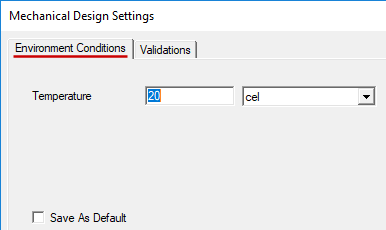
- In the Environment Conditions tab, specify the desired environment (stress-free) Temperature value and use the adjacent drop-down menu to choose the Units.
- Click OK.
The Thermal Condition dialog box appears.
You do not have to assign the environment temperature to objects that are not either hotter or colder than the EnvTemp value. Objects with no Thermal Condition assignment are assumed to be at the environment temperature (which is the stress-fee temperature).
If you type in a new variable name (that is, one not previously defined), the Add Variable dialog box appears. Specify the Unit Type, Unit, and Value in this dialog box and then click OK.
The algorithm used to map temperature values from the source model to the target model is the System Coupling (SyC) Mapper and is based on the Radial Basis Functions (RBF). For more information concerning system coupling details, visit the Ansys System Coupling homepage (Ansys account signon required). Then do the following:
This user guide is comprehensive and includes coverage of loads that are not applicable to Mechanical – Structural analyses.
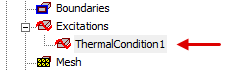
The assigned Thermal Condition appears under Excitations in the Project Manager:
Sometimes, the stress-free temperature of an assembly may be considerably hotter than the temperature of the environment in which the assembly operates. For example, consider a printed circuit board heated by the molten solder applied during a wave-soldering operation. After the solder cools to its fusion temperature and the assembly continues to cool off, thermal stresses are induced by the shrinkage of the solder. In this case, the board is in a state of residual stress at room temperature, and the stress is reduced if the solder is heated. In such cases, you can set the EnvTemp value to a temperature near the point where the solder develops a significant stiffness, assign something close to room temperature to the model's objects, and thereby determine the residual stresses in the assembly.
Verifying Thermal Condition Linking
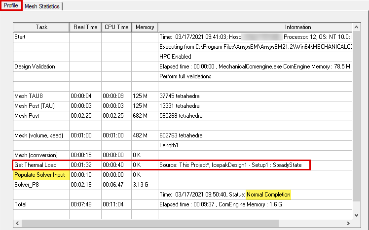
When you have assigned a Non-Uniform Thermal Condition, you can verify that the temperature mapping has been performed successfully from the analysis profile:
- Under Analysis in the Project Manager, right-click the target setup and choose Profile from the shortcut menu.
After Mesh (conversion), the Get Thermal Load process is listed, including the source project and source design information. This profile entry represents the temperature mapping process. When this step is successfully completed, it is followed by Populate Solver Input, and the solution proceeds:
Best Practices:
When you assign a Non-Uniform Thermal Condition, the application does not enforce an identical geometry limitation between the source and target designs. The mapping scheme provides some flexibility. However, your results may be unpredictable and incorrect if there is not a very close correlation between objects in the source design and corresponding objects with imported temperatures in the target design. Follow these best practice guidelines for accurate and reliable results:
- Though not a requirement, it is best to keep the number of Thermal Condition objects in the source and target designs the same. Doing so keeps the designs straightforward and helps to minimize the likelihood of errors.
- The geometry (volume, shape, orientation, and absolute location in global coordinates) of each corresponding pair of source and target objects should be consistent between the source and target designs.
- The mesh quality should be comparable between the source and target objects.
Source and target meshes cannot be identical between Icepak and other design types. Icepak employs a unique meshing process. However, the mesh sizing can be similar between the source and target designs.
When using a Mechanical–Thermal solution for the temperature source, you can take advantage of mesh linking. This method provides identical meshes between source and target designs and also reduces the solution time by skipping a second mesh generation phase.
Thermal Condition mapping is performed on the basis of the locations of the element centroids in the source and target objects. Therefore, you do not have to specify the source object that is associated with each target object. For this reason, you can assign a Thermal Condition excitation to multiple target objects in a single operation.
Cached Link Data and Solution Invalidation
The temperatures from the source design are cached in the target design after its simulation. You can remove this cached data (instructions below).
If you've updated the source design and want the imported temperatures in the target design to reflect the changes in the source project, you need to clear the linked data. Doing so invalidates the previous solutions. Clear the linked data using one of the following two methods:
Method 1: (to clear linked data and/or solutions)
- Using the menu bar, click Mechanical > Results > Clean Up Solutions.
The Clean Up Solutions dialog box appears.
- In the Solutions section of the dialog box, choose one of the following sets of options:
- Select the Linked Data Only option.
- Select the Fields and Meshes and Include Linked Data options.
- Select the All Solutions and Include Linked Data options.
- Click Do Deletions.
Method 2: (to clear linked data only)
- Under Analysis in the Project Manager, right-click a solution setup and choose Clear Linked Data from the shortcut menu.
- Current Thermal Condition temperatures and previously solved results are invalidated when the cached data is cleared.
- Temperatures are cached for each solution setup with a Thermal Condition excitation specified.
- The cached data is automatically cleared when the target Mechanical design is edited in a way that invalidates its results (such as adding, removing, or modifying geometry).
- Cached link data in the target (Mechanical) design is not automatically removed when the source design is edited.