
Mesh Linking
Importing a mesh allows a Mechanical simulation (target design) to be solved using the meshes created from a previously completed simulation (source design). The Mechanical simulation time can be reduced by eliminating the time spent on creating a mesh. Additionally, matched meshes improve the accuracy of mapping for imported EM Loss excitations in Thermal solutions.
You can import a mesh from another design in the same project file or from a different project.
Mesh linking will work if the following two conditions are satisfied:
- Both designs have matching object names.
- Both designs have identical geometry (based on each object having the same model history).
See Mesh Linking Requirements below for more information.
You can import meshes from the following types of source designs into a Mechanical target design:
- Mechanical
- HFSS
- Maxwell 3D
- You cannot import a mesh from a Mechanical–Thermal source design (either Steady-State or Transient) if it includes any Thermal Contact assignments, unless the target design is also one of the two Mechanical–Thermal solution types. The specific source and target solution types do not have to match. That is, one can be steady-state and the other transient. An additional requirement is that the target Thermal design must have Contact assignments at the same faces as the source design, though the thermal resistance values can differ between the source and target designs.
- You cannot import a mesh from an HFSS source design that includes an IE or PO Region.
- Source designs can include sheet objects, and the sheet objects must remain active model objects in the Mechanical target design for mesh linking to work.
- HFSS FE-BI and Dielectric Cavity types of Hybrid Regions and other vacuum or air regions in source designs are supported for mesh linking.
- Thermal Solutions: For such regions in Thermal solutions, clear the Solve Inside attribute in the region's properties.
- Modal and Structural Solutions:, Avoid mesh linking from source design that contain such air or vacuum regions. The reasons are as follows:
- If you were to include an air or vacuum region, you would have to define very small, arbitrary, non-zero Mass Density and Young's Modulus values in the material properties, along with an arbitrary Poisson's Ratio value. For Modal solutions, the region would move with the solid objects as they vibrate, and the additional mass and stiffness, though small, could somewhat skew the Modal results. You might also encounter vibration modes in the air or vacuum regions themselves.
- Mesh linking will fail if you set included vacuum or air regions to non-model objects (that is, if you clear the Model attribute in the object properties). It will fail because the active geometries are no longer identical between the two designs.
- Clearing the Solve Inside attribute would prevent mesh linking from failing. But, if you don't solve inside the air or vacuum region, no displacement can occur. That is, the region will behave as a rigid body. Therefore, nothing in contact with the region would be able to deform. Mode shapes and frequencies could not be determined, thermal expansion or contraction would be prevented, and thermal stress results would be incorrect.
- The source and/or target designs can contain 3D Components if they're not encrypted. When an encrypted 3D Component is involved, mesh linking is only supported when the source and target design type and solution type are the same (for example, Mechanical – Thermal source and Mechanical – Thermal target).
For all Mechanical designs (Modal, Thermal, and Structural solutions), you cannot assign boundaries or excitations to sheet objects. These objects are ignored by the solver.
For Thermal solutions only, you can select the Shell Element attribute in a sheet object's properties, and then you can assign it boundaries and excitations. Shell object participate in thermal solutions.
The ambient air or fluid around solid objects is generally represented by Convection boundaries. Specified or imported convection film coefficients take into account the effect of fluid motion along the convection surfaces. Clearing the Solve Inside attribute prevents redundant heat conduction through the region, which would occur in parallel with the convection boundary's effects.
Mesh linking will work when you choose not to solve inside an object. Conversely, deleting the region or setting it as a non-model object (by clearing the Model attribute), would prevent mesh linking from working, because the active source and target geometry would no longer be identical.
How to Import a Mesh:
Prior to importing a mesh, ensure that you have created an exact duplicate of the source model geometry and object names by following the steps outlined under Mesh Linking Requirements.
Mesh linking is set up as part of specifying the Solution Setup. The settings for importing a mesh are found under the Advanced tab of the Modal Solve Setup, Thermal Solve Setup, or Structural Solve Setup dialog box:
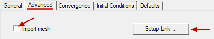
- Select the Import mesh option.
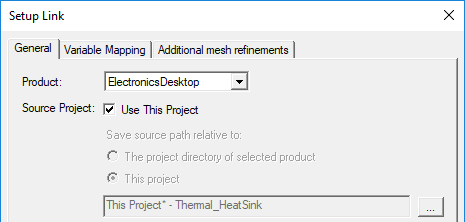
- If the mesh is to be imported from a design in the same project:
- Select Use This Project:
- Skip to step 5.
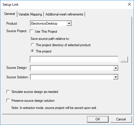
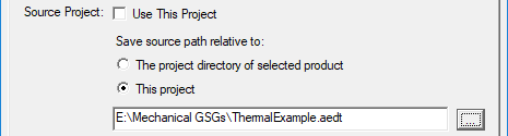
- Otherwise, if the mesh source is to be from a different project, clear Use This Project. The Mechanical design saves the relative path to the source project in one of two ways.
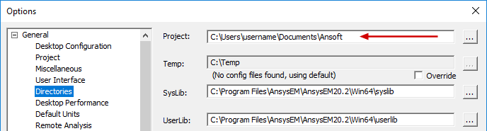
- The project directory of selected product: Save source project path relative to the default Project folder specified in the Options dialog box (Tools > Options > General Options):
- This project: Save source project path relative to the target project location.
- Click the ellipsis button ( ... ).
- Locate the source project file and select it.
- Click Open.
- Choose the Source Design and Source Solution from the provided drop-down menus:
- Optionally, select one or both of the following two options:
- Simulate source design as needed: Select this option if you want an updated source mesh to be linked to the target design when the source design has been modified.
- Preserve design solution: When the source design is in a separate project, and that project is closed, the source design will not be saved (preserving the preexisting solution data). This option is not applicable if the source design is in the same project as the target design.
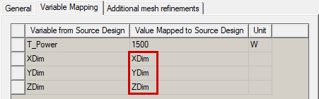
- Click the Variable Mapping tab.
- Optionally, to keep the source and target design variables synchronized, click Map Variable by Name. Then, the same variable names will appear in both columns, and the values will remain synchronized between the two mesh-linked analyses.
- Variables can only be mapped by name if they already exist in the Mechanical design. When you copy and paste geometry from the source, or import it from the clipboard, variables used in the definition of the geometry automatically come into the Mechanical design. However, for non-geometry-related variables (such as a variable voltage or wattage applied to an excitation in the HFSS Edit post process sources dialog box), the variables will not automatically appear in the Mechanical design. There is no consequence to this limitation though, since only variables that affect the geometry will affect the modal results.
- When the Value Mapped to Source Design column contains constants, those constant values will be passed to the source design even if you change the associated variable's value in the target design's Properties dialog box (Mechanical > Design Properties) or in the docked Properties window (with the target design selected in the Project Manager).
- If you have not mapped the detected variables by name, you will be prompted with a warning upon attempting to close the Setup Link dialog box. The warning will allow you to return to the Variables Mapping tab to click the Map Variable by Name button. Alternatively, you can accept the unsynchronized variables and close the dialog box.
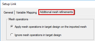
- In the Additional mesh refinements tab of the Setup Link dialog box, choose one of the following two options:
- Apply mesh operations in target design on the imported mesh
- Ignore mesh operations in the target design
- Changing the Additional mesh refinement settings does not invalidate the cached link data (meshes from source design).
- When the source and target for mesh linking are both Mechanical–Thermal designs in which one or more Thermal Contact assignments exist, mesh operations cannot be performed in the target design. If you attempt to do so by selecting the first option, a warning message is produced stating that mesh operations cannot be performed on the target design. The warning message won't prevent the solution from running. The solution will be based on the unmodified imported mesh.
- Click OK to close the Setup Link dialog box.
- If you are done with the thermal solution setup, click OK to close this dialog box too.
- Optionally, for Thermal solution models including an imported vacuum, fluid, or air region that you want to exclude from participating in the thermal solution, select that object in the History Tree. Then, in the docked Properties window, clear the Solve Inside option.
The Setup Link dialog box appears if a link hasn't been specified previously:
It is convenient to include source and target designs within the same project. Doing so keeps all project files in the same location and is the most convenient and straightforward way to organize linked designs. However, this approach may be impractical when there is a large number of designs in the project.
Choose one of the following two options under Save source path relative to:
The Open dialog box appears. Then:
The selected project is listed in the Setup Link dialog box:
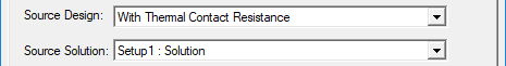
These two settings are automatically populated with an available design and solution in the source project. However, if more than one other design or solution exists in the source project, you can manually select the desired ones (if different from the automatically selected design or solution).
In the Extractor mode, the source project will be saved upon exit. Extractor mode means that the source project is opened during the link solely for the purpose of solving.
If design variables have been defined in the source design, they are listed in the Variable from Source Design column. Initially, the nominal value of each variable is listed in the Value Mapped to Source Design column:
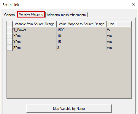
The values passed back to the source design from the mechanical design (second column) can either be constants (numerical values), variables, or expressions. The specified values determine the variation from which the source design provides the linked data.
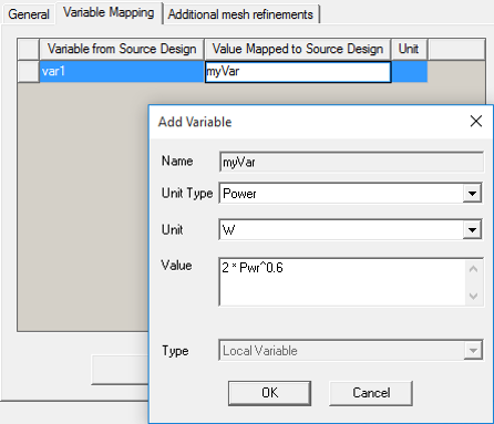
Automatic variable creation is supported in the Variable Mapping tab. You can directly type a new variable name into the Value Mapped to Source Design column, and the Add Variable dialog box will appear, in which you can define the Units and Value of the variable. The specified value can be a constant, a variable name, or an expression.
(depending on whether or not you want the target Mechanical solution to perform further mesh refinement on the imported mesh).
If you define a link setup for importing a mesh and later revisit the Link Setup dialog box, it will be in View Only mode. The settings will be displayed but unavailable for editing. Select the Edit Link option under the General tab to return the dialog box to the editing mode.
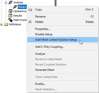
If you want to import the mesh from an existing solution setup to a new solution setup in the same design, a command is available to automate the process. The program can automatically create a new target solution setup that is configured to link to, and import the mesh from, the source solution setup. To use this feature, do the following:
- Under Analysis in the Project Manager, right-click the existing solution setup that you want to use as a mesh source for a new setup.
- Choose Add Mesh Linked Solution Setup from the shortcut menu:
- Optionally, edit the settings in the new analysis setup as desired.
The new setup is added under Analysis in the Project Manager. If you look at the properties of this new setup, you will see that the link to the setup that you initially right-clicked is already defined.
Verifying Mesh Linking
There are two ways to verify that mesh linking has been performed after the source and target setups have been analyzed:
- Under Analysis in the Project Manager, right-click the target setup and choose Profile from the shortcut menu.
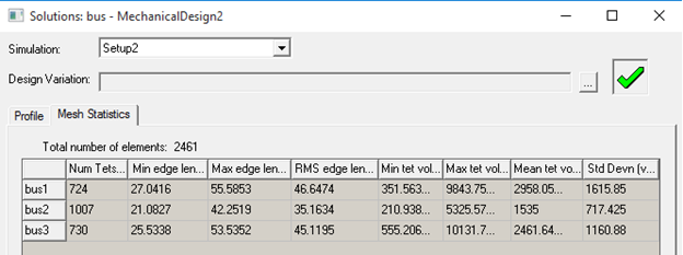
- Under Analysis in the Project Manager, right-click each of the setups in turn (source and target) and choose Mesh Statistics. The mesh statistics should be identical between the two designs, providing you haven't solved the second setup with additional mesh operations (refinements) defined.
The mesh import step is listed in the profile:
![]()
Mesh Linking Requirements
As stated previously, you can reuse a mesh from an existing source design in a target design if all objects have matching names and identical geometry (based on each object having the same model history in both designs). The easiest way to achieve this result is to copy and paste the items from one design into the other. The objects will be supported for mesh linking regardless of the order of the copy/paste operations.
In the following procedure, all objects are copied and pasted from one design to the other in a single operation:
- If your source and target model are both Mechanical designs, copy and paste the complete design, as follows:
- In the Project Manager, right-click the source design and choose Copy.
- Also in the Project Manager, right-click the project name and choose Paste.
- Edit the Solution Type if needed (for example, if the source design is a Mechanical – Thermal solution, and the target is to be a Structural solution).
- If your source and target model are different design types:
- Select all of the objects in the source design using one of the following three methods:
- In Object selection mode, click in the Modeler window of the source design to ensure that it's the active window and then press Ctrl+A.
- In the History Tree of the source design, right-click Model and choose Select All.
- In the Object selection mode, click and drag the mouse to draw a selection box enclosing all source model objects.
- Copy the selected objects to your Clipboard using one of the following four methods:
- Press Ctrl+C.
- On the View, Draw, or Model ribbon tab, click
 Copy.
Copy. - Right-click the Modeler window and select Edit > Copy from the short-cut menu.
- Using the menu bar, click Edit > Copy.
- In the target design, use one of the following four methods of pasting the objects:
- Click in the display area of the Modeler window and press Ctrl+V.
- On the View, Draw, or Model ribbon tab, click
 Paste.
 - Right-click the Modeler window and select Edit > Paste from the short-cut menu.
- Using the menu bar, click Edit > Paste.
If you draw the selection window from left-to-right, you must fully enclose every object. If you draw it from right-to-left, every object that the window encloses and those that it crosses through are selected. So, in the latter case, the selection window does not have to fully enclose every object in the model to select them all.
The Import from Clipboard command in the Modeler menu is still available for copying source geometry into a target design. However, it is no longer required to make mesh-linking-compliant geometry. Using this command can have unexpected consequences, as it clears the History Tree.
After you create the duplicate model using one of the above methods, create a Solution Setup in the target design. Use the procedure outlined previously under How to Import a Mesh.
Cached Link Data and Solution Invalidation
The meshes from the source design are cached in the target design after its simulation. You can remove these cached meshes (instructions below).
If you've updated the source design and want the imported mesh in the target design to reflect the changes in the source project, you need to clear the linked data. Doing so invalidates the previous solutions. Clear the linked data using one of the following two methods:
Method 1: (to clear linked data and/or solutions)
- Using the menu bar, click Mechanical > Results > Clean Up Solutions.
- In the Solutions section of the dialog box, choose one of the following sets of options:
- Select the Linked Data Only option.
- Select the Fields and Meshes and Include Linked Data options.
- Select the All Solutions and Include Linked Data options.
- Click Do Deletions.
The Clean Up Solutions dialog box appears.
Method 2: (to clear linked data only)
- Under Analysis in the Project Manager, right-click a solution setup and choose Clear Linked Data from the shortcut menu.
This action will clear all linked data in the target design. For example, if your design has two EM Loss links and three solution setups that each include a mesh link, data from all five links will be cleared.
- Current meshes and previously solved results are invalidated when the cached mesh is cleared.
- Meshes are cached for each solution setup with an imported mesh specified.
- The cached mesh is automatically cleared when the target Mechanical design is edited in a way that invalidates its mesh (such as adding, removing, or modifying geometry).
- Cached meshes in the target (Mechanical) design are not automatically removed when the source design is edited.