
EM Loss
You can import electromagnetic (EM) losses from other Ansys Electronics Desktop designs to use as thermal excitations in the target Mechanical – Thermal design. EM Losses may be volumetric or surface based depending on the associated source object. You can assign EM losses to only the following entity type:
- Objects (solid or shell)
You can import EM losses from another design in the same project file or from a different project. The program first looks for a source object with the same name as the target object. The program attempts to determine the type of loss (surface or volume) from the properties of source objects with the same name as the target objects. However, actual EM loss mapping is done based solely of the X, Y, and Z locations of the element centroids.
The source and target object names, geometry, and meshes do not have to match exactly. However, you will obtain the best results when the source and target geometry is the same, and the mesh quality and element densities (fineness or coarseness) are very similar. For this reason, you may want to take advantage of mesh linking. The exception, of course, is when you are importing EM losses from a Maxwell 2D model to your Mechanical–Thermal model, which is always 3D.
You can import EM loss data from the following types of source designs into a Mechanical – Thermal target design:
- HFSS: From Modal, Terminal, or Eigenmode solutions – import surface losses from non-solve-inside conducting objects and volume losses from solve-inside lossy objects.
- Maxwell 3D: Surface losses from Impedance boundaries, and volume losses from solve-inside conducting objects
- Maxwell 2D: Losses can be mapped from a 2D model that lies on the global XY plane to a Mechanical–Thermal target model. The end face of the solid geometry must match the 2D model. The 3D model can be an extrusion of the end face geometry in either the +Z or the -Z direction, and the extrusion can include swept motion or rotation in the X and Y directions. To clarify these statements, considering the following image comparing a 2D model of an electric motor (with half-symmetry about the XZ plane) and a corresponding 3D model (with half-symmetry about the XY plane). Notice how the windings are extruded along a path with both axial and tangential progression:
- Q3D: Surface losses from conducting objects for the AC field type, and volume losses from lossy objects for the DC field type
However, you cannot import EM Losses from HFSS source designs that include an IE or PO Region.
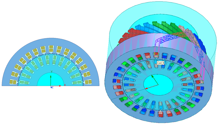
The features of the 2D model are exactly represented on the same plane in the 3D model. The program mirrors the half-symmetry results and applies the loss to the full set of 3D objects extruded from the faces lying along the XY plane. Note that RMxprt provides a way to export solved models as either Maxwell 2D or Maxwell 3D designs. The geometry for a Mechanical design can be copied from a Maxwell 3D design’s geometry. Either the corresponding Maxwell 2D or Maxwell 3D design can be used as the source model for EM Losses in the Mechanical–Thermal solution.
The 2D solution assumes that the geometry is extruded purely in the Z direction. Therefore, for models such as in this example, 2D-to-3D mapping of losses is less accurate than a 3D-to-3D coupling of identical geometry. However, the solution time is much shorter, and the accuracy sufficient for initial rough-design phases.
- Lossy objects are those with material definitions that include a Dielectric Loss Tangent greater than zero.
- You can apply multiple EM Loss excitations to the same object, each importing the EM Loss from a different design. Use this capability to superimpose EM Losses (for example, combining volume losses from Q3D with surface losses from HFSS), to see the thermal effects when two or more EM Losses are combined.
- You can scale each imported EM Loss excitation by a user-defined multiplier. For example, you could increase the imported loss by a factor of 1.25 to build a 25% safety margin into your thermal solution.
- You can offset volumetric and surface-based EM Loss excitations with Heat Generation or Heat Flux excitations applied to the same volumes or surfaces, respectively. The offset excitation can increase or decrease the EM Loss excitation.
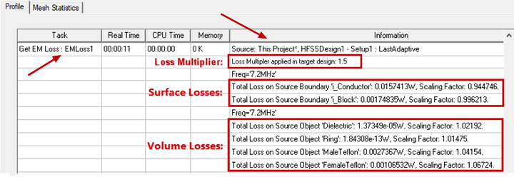
- A summary of coupled EM Loss data can be viewed on the Profile tab of the Solutions dialog box during the solution process. In the Project Manager, expand Analysis, right-click the solution setup, and select Profile.
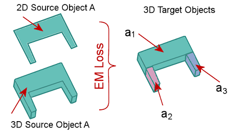
Ideally, there should be a one-to-one correlation between source 2D or 3D objects and target 3D objects. However, it is possible for a source object to correspond to multiple smaller objects in the target design, with the combination of the target objects corresponding to the larger source object, as shown in the following example:
You must handle this situation in a particular way:
- Specify the EM Loss between the single source object (“A”) and the multiple corresponding target objects (“a1,” “a2,” and “a3”) in a single excitation. If you look at the properties of the EM Loss assignment, it must resemble the following image (with a single excitation (EMLoss_A) including all three volumes as targets:
- Conservation of loss is enforced at the object level for each individual EM Loss excitation. That is, the total loss of the target objects always equals the total loss of the source objects for each EM Loss excitation. If you were to assign the EM loss of a large source object to multiple, smaller target objects in separate excitations (A‑to‑a1, A‑to‑a2, and A‑to‑a3), each of the smaller target objects would receive the full EM loss of the larger source object (“A”), thus exaggerating the total EM loss in the target design, and the solution results would be incorrect.

How to Assign an EM Loss Excitation:
- Select one or more target objects to which you want to apply imported EM losses. Whether the linked EM losses will be surface-based or volumetric, you always assign them to objects.
- Begin applying an EM Loss excitation using one of the following three methods:
- Right-click in the Modeler window or on a selected object in the History Tree and choose Assign Excitation > EM Loss from the shortcut menu.
- Right-click Excitation in the Project Manager and choose Assign > EM Loss.
- Using the menu bar, click Mechanical > Excitations > Assign > EM Loss.
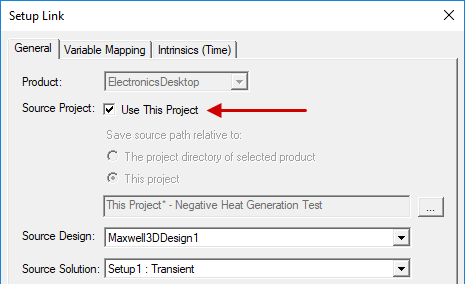
- If the EM loss data is to be imported from a design in the same project:
- Select Use This Project:
- Skip to step 6.
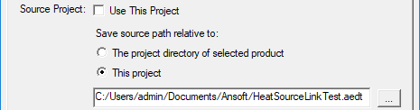
- Otherwise, if the EM loss data is to be imported from a different project, clear Use This Project.
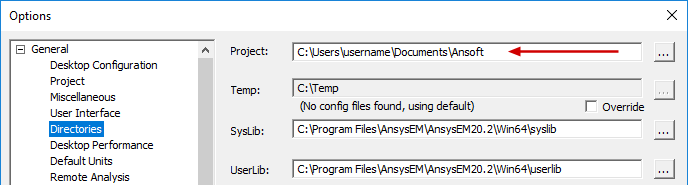
- The project directory of selected product: Save source project path relative to the default Project folder specified in the Options dialog box (Tools > Options > General Options):
- This project: Save source project path relative to the target project location.
- Click the ellipsis button ( ... ).
- Locate the source project file and select it.
- Click Open.
- Choose the Source Design and Source Solution from the provided drop-down menus:
- Optionally, select one or both of the following two options:
- Simulate source design as needed: Select this option if you want an updated solution to be linked to the target design when the source design has been modified.
- Preserve design solution: When the source design is in a separate project, and that project is closed, the source design will not be saved (preserving the preexisting solution data). This option is not applicable if the source design is in the same project as the target design.
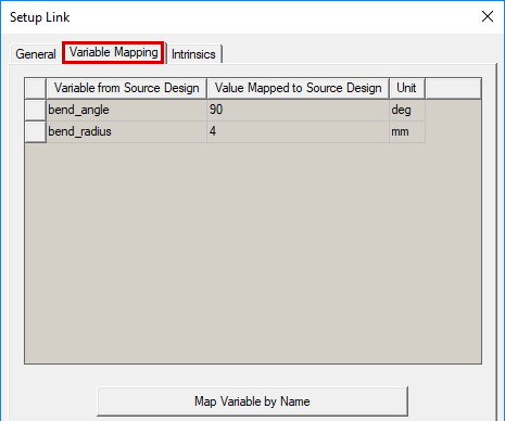
- Click the Variable Mapping tab.
- Optionally, to keep the source and target design variables synchronized, click Map Variable by Name. Then, the same variable names will appear in both columns, and the values will remain synchronized between the two coupled analyses.
- Variables can only be mapped by name if they already exist in the Mechanical design. When you copy and paste geometry from the source, or import it from the clipboard, variables used in the definition of the geometry automatically come into the Mechanical design. However, for non-geometry-related variables (such as a variable voltage or wattage applied to an excitation in the HFSS Edit post process sources dialog box), you would have to manually define the variable within the Mechanical design.
- When the Value Mapped to Source Design column contains constants, those constant values will be passed to the source design even if you change the associated variable's value in the target design's Properties dialog box (Mechanical > Design Properties) or in the docked Properties window (with the target design selected in the Project Manager).
- If you have not mapped the detected variables by name, you will be prompted with a warning upon attempting to close the Setup Link dialog box. The warning will allow you to return to the Variables Mapping tab to click the Map Variable by Name button. Alternatively, you can accept the unsynchronized variables and close the dialog box.
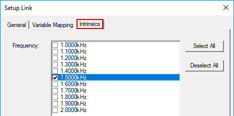
- Source designs may provide EM losses at multiple frequencies when they are set up appropriately. In such cases, click the Intrinsics tab and select one or more frequencies from the Frequency list. Your selection defines the solution frequency (or frequencies) in the source design from which you wish to import the EM losses as a source of heat in the Mechanical – Thermal design. (See Important note below.)
- For Maxwell transient solutions (Magnetic or Electric), click the Intrinsics (Time) tab and select the desired Start Time and End Time from the drop-down menus.
- Click OK to close the Setup Link dialog box.
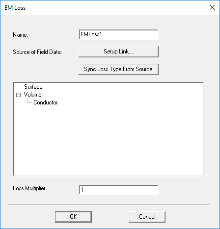
- Optionally, specify a customized Name for the EM loss excitation.
- Optionally, specify a Loss Multiplier other than 1 (<1 to decrease the imported loss, >1 to increase it).
- As needed, drag and drop the listed objects to place them under Surface or Volume, specifying the type of EM loss.
- The program will attempt to determine the appropriate loss type (Surface or Volume) based on the source design's object properties. Verify that the automatic assignments are correct and modify them as needed. You can click and drag objects from one loss type to the other.
- If you've changed the EM loss type of any object between Volume and Surface and wish to restore the automatic assignments, click Sync Loss Type From Source. This command is also useful for reevaluating the loss type after the source design has been modified.
- Click OK to close the EM Loss dialog box.
- If you double-click the EM Loss entry in the Project Manager (or right-click it and choose Properties), The EM Loss dialog box will reappear for editing the excitation.
- To edit the EM loss link, click Setup Link, which will open the Setup Link dialog box. When revisiting this dialog box, it will be in View Only mode. The settings will be displayed but unavailable for editing. Select the Edit Link option under the General tab to return the dialog box to the editing mode.
- If the properties of objects in the source design have been edited, you can click Sync Loss Type From Source to reevaluate the loss type categorization.
The Setup Link dialog box appears:
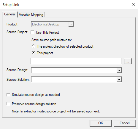
It is convenient to include source and target designs within the same project. Doing so keeps all project files in the same location and is the most convenient and straightforward way to organize linked designs. However, this approach may be impractical when there is a large number of designs in the project.
The Mechanical design saves the relative path to the source project in one of two ways. Choose one of the following two options under Save source path relative to:
The Open dialog box appears. Then:
The selected project is listed in the Setup Link dialog box:

These two settings are automatically populated with an available design and solution in the source project. However, if more than one other design or solution exists in the source project, you can manually select the desired ones (if different from the automatically selected design or solution).
If you will be performing a two-way coupled simulation, you must select both of these options.
Certain changes to the source design may not invalidate its solution. In these cases, a new source solution will only be run if the previous one did not converge. To achieve convergence, you may have to increase the specified maximum number of passes or relax the convergence criterion in the source solution setup.
(Also, see Cached Link Data and Solution Invalidation below for additional considerations).
In the Extractor mode, the source project will be saved upon exit. Extractor mode means that the source project is opened during the link solely for the purpose of solving.
If design variables have been defined in the source design, they are listed in the Variable from Source Design column. Initially, the nominal value of each variable is listed in the Value Mapped to Source Design column:
The values passed back to the source design from the mechanical design (second column) can either be constants (numeric values), variables, or expressions. The specified values determine the variation from which the source design provides the linked data.
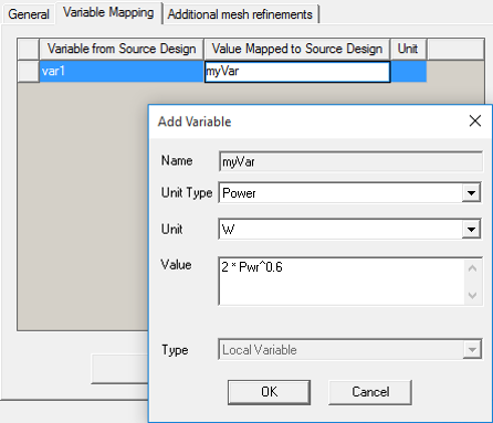
Automatic variable creation is supported in the Variable Mapping tab . You can directly type a new variable name into the Value Mapped to Source Design column, and the Add Variable dialog box will appear, in which you can define the Units and Value of the variable. The specified value can be a constant, a variable name, or an expression.
.png)
Mapping variables to the source design by name is useful for Optimetrics analyses (for cases where changing the value of a variable affects both the target design and the EM losses from the source design). You can create an Optimetrics setup in the target design that sweeps both the target and source designs.
Multiple frequencies are available from HFSS designs (Modal and Terminal solution types only) and Maxwell 3D designs (Eddy Current solutions), providing that you include a frequency sweep and choose to save the fields for all frequencies.
When you select multiple frequencies, the EM losses are additive. That is, the excitations for each frequency are considered to be occurring simultaneously. Therefore, the thermal solution and any field reports or overlays you create are based on the total combined EM losses of all the selected frequencies.
To see the thermal effects of a single excitation frequency, solve the Mechanical – Thermal design with only one frequency at a time selected under the Intrinsics tab.
.png)
The Mechanical solution is based on the total energy loss in the source design during the period you specify in the Intrinsics (Time) tab divided by the same specified time period. This quotient is the average power loss that will be applied to the target thermal solution as a constant EM Loss.
The EM Loss dialog box appears:
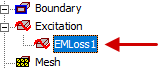
The EM loss assignments appear under Excitation in the Project Manager.
Verifying EM Loss Linking
You can verify that EM loss mapping has been performed after the source and target setups have been analyzed:
- Under Analysis in the Project Manager, right-click the target setup and choose Profile from the shortcut menu.
The retrieval of external EM loss data is reported in the simulation profile. Surface and volume losses are grouped separately:
Best Practices:
The application does not enforce an identical geometry limitation between the source and target designs for EM loss linking. The EM loss mapping scheme provides some flexibility. However, your results may be unpredictable and incorrect if there is not a very close correlation between objects with EM losses in the source design and corresponding objects with imported EM losses in the target design. Follow these best practice guidelines for accurate and reliable results:
- Though not a requirement, it is best to keep the number of EM loss objects in the source and target designs the same. Doing so keeps the designs straightforward and helps to minimize the likelihood of errors.
- The geometry (volume, shape, orientation, and absolute location in global coordinates) of each corresponding pair of source and target objects should be consistent between the source and target designs.
- The mesh quality should be comparable between the source and target objects.
The source and target meshes do not have to be identical. However, you can take advantage of an imported mesh to reduce solution time and to ensure identical geometry, which is enforced for mesh linking. (See the Mesh Linking topic for more information. For instructions on creating identical geometry in the target design, see the Mesh Linking Requirement section of the same topic.)
EM loss mapping is performed on the basis of the locations of the element centroids in the source and target objects. Therefore, you do not have to specify the source object that is associated with each target object. For this reason, you can assign EM loss excitation to multiple target objects in a single operation.
Cached Link Data and Solution Invalidation
The EM losses from the source design are cached in the target design after its simulation. You can remove this cached data (instructions below).
If you've updated the source design and want the imported EM losses in the target design to reflect the changes in the source project, you need to clear the linked data. Doing so invalidates the previous solutions. Clear the linked data using one of the following two methods:
Method 1: (to clear linked data and/or solutions)
- Using the menu bar, click Mechanical > Results > Clean Up Solutions.
- In the Solutions section of the dialog box, choose one of the following sets of options:
- Select the Linked Data Only option.
- Select the Fields and Meshes and Include Linked Data options.
- Select the All Solutions and Include Linked Data options.
- Click Do Deletions.
The Clean Up Solutions dialog box appears.
Method 2: (to clear linked data only)
- Under Analysis in the Project Manager, right-click a solution setup and choose Clear Linked Data from the shortcut menu.
- Current EM losses and previously solved results are invalidated when the cached data is cleared.
- EM losses are cached for each solution setup with an EM loss excitation specified.
- The cached data is automatically cleared when the target Mechanical design is edited in a way that invalidates its results (such as adding, removing, or modifying geometry or changing the solution setup to import a mesh).
- Cached link data in the target (Mechanical) design is not automatically removed when the source design is edited.