
Adding a Layout Component
Layout components are a beta feature supported for steady-state and transient solution types.
For information on enabling beta options, see General Options: Desktop Configuration.
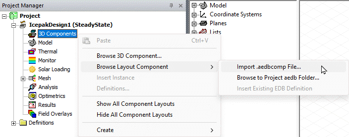
- In the Project Manager, right-click 3D Components and access the Browse Layout Component flyout menu:
- Import .aedbcomp File: Choose this option if you have exported an HFSS 3D Layout as a single-file Layout Component (*.aedbcomp).
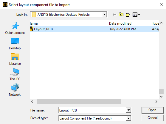
- Browse to the location of the desired *.aedbcomp file.
- Select the file.
- Click Open to complete the component source file selection.
- Browse to Project .aedb Folder: Choose this option to specify the location of an Ansys electronics database folder (*.aedb) to use in the creation of the layout component. This folder is where HFSS 3D Layout design filesets are stored.
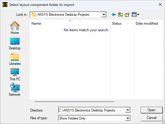
- Browse to the *.aedb folder that contains the desired layout.
- Double-click the folder to open it.
- Click Open to complete the component source folder selection.
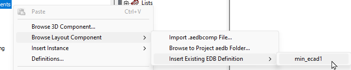
- Insert Existing EDB Definition shows a list of existing EDB definitions available within the project.
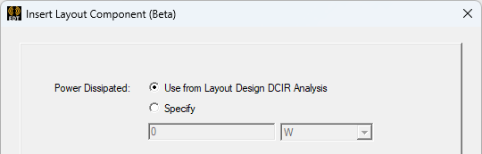
- On the Property tab, select an option to define the Power Dissipated. Power dissipated specifies the total power dissipated by the layout component.
- Use from Layout Design DCIR Analysis specifies the power based on the EM loss results in the linked HFSS 3D Layout design.
- Specify defines a uniformly dissipated total power.
- On the Board tab, define the metal fraction, geometry, and material properties of the layout component.
- Specify the metal fraction map's Resolution using one of the following two methods:
- Drag the slider left (coarser) or right (finer) to specify the number of divisions along the shorter dimension of the component, whether vertical or horizontal.
- Select Custom and specify the number of Columns and Rows to divide the board into for mapping purposes.
- Choose the desired Extents option:
- Bounding Box: The bounding box of the source layout design
- Polygon (if available): The largest outline layer polygon of the source layout design
- Optionally, choose the desired Board Cutout Material and Via Hole Material.
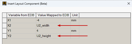
- What appears on the Variable Mapping tab depends on whether variables are defined in the source layout. Choose one of the following two actions:
- If there are no applicable variables in the source layout, the Parameters tab has no variables listed.
- When applicable variables are present in the source layout, the Variable Mapping tab, do one of the following:
- Optionally, you can substitute local variable names for the numeric values in the Values Mapped to EDB column. This is particularly useful if you wish to include multiple instances of the layout component in a single design and have geometry variations between the instances. See Instance Variation for more information.
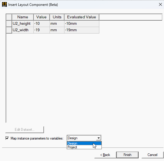
- On the Parameters tab, if you chose not to define local variables on the Variable Mapping tab, or if the source design contains no variables, none will be listed on the Parameters tab.
- Otherwise, when you have defined local variables on the Variable Mapping tab, they will be listed on the Parameters tab along with their values and units.
- Optionally, toggle the selection of Map instance parameters to variables as preferred.
- If Map instance parameters to variables" is selected, choose either Design or Project from the adjacent drop-down menu to specify the type of local variable to create.
- Click OK.
- Optionally, to change the visualization characteristics of the layout component, do the following:
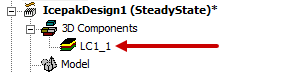
- Under 3D Components in the Project Manager, select the <layout_component_name>.
- In the docked Properties window, select the Visualization tab.
- If you visited the Object Attributes dialog box, click OK to apply your settings and to close the dialog box.
- In object selection mode, select all layers of the layout component and assign a length-based mesh operation on the selection. Set the maximum element length to be three to four times the width or height of the grid cells, whichever is the lesser.
Then, choose one of the following three commands and follow the associated instructions:
A Select layout component file to import dialog box appears:
A Select layout component folder to import dialog box appears:
Selecting an .aedbcomp file, .aedb folder, or an existing EDB definition opens the Insert Layout Component (Beta) dialog.
The Insert Layout Component dialog General tab appears:
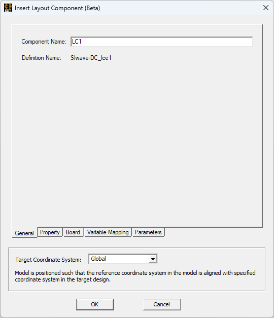
The General tab page allows you to specify a target coordinate system. From the Target Coordinate System drop-down list, select the coordinate system on which to place the layout component. Relative coordinate systems defined in the target design appear in the drop-down list.
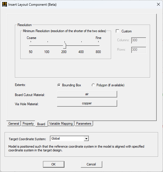
The resolution along the longer dimension is proportional to the specified slider value. Specifically, it is an integer calculated from the slider value times the long/short dimension ratio of the component. Therefore, each cell will always be approximately square (width ≈ height) when using the slider.
Columns refers to the number of divisions along the horizontal (X direction), and Rows refers to the vertical (Y direction) divisions, regardless of which dimension is larger.
See the "Important" guidelines in the Trace Mapping topic for resolution recommendations.
Board Cutout Material specifies the material assigned to the board cutout geometry, if it exists. Board cutout geometry exists if Polygon is selected for Extents, and that polygon contains void polygon(s). The cutout geometries are created from those void polygon(s). The default board cutout material is that of the global mesh region if present in the model. Otherwise, the default board cutout material is set to air-solid.
The default material for via holes is copper.
Skip to step 5.
If you do specify a previously undefined local variable name, the Add Variable dialog box will appear when you press Enter so that you can define its unit type, units, and initial value in-place.
In the following example, two of the four variables in the source ECAD database (X2 and Y2) have had local variables substituted for the original numeric values:
If you wish to specify a project variable name, you do not have to prefix the variable name with a dollar sign ($). On the next tab, you can choose whether to create Design or Project variables, and the name will be automatically prefixed with a dollar sign for the latter type.
Skip to step 5.
The following figure shows the parameters with two local variables substituted for numeric values.
You can choose whether to keep these mapped variables only as instance parameters or to also create local Design variables or Project variables, as follows:
If this option is cleared, mapped geometry variables are exposed in the Icepak design only as layout component parameters, and you can vary the values between multiple instances of the component in the same design.
Alternatively, if you also wish to include the mapped variables as Icepak design or AEDT project variables, select this option and choose between the two types in the next step.
As previously stated, the variable name will be prefixed with a dollar sign ($) automatically when you choose to create local Project variables.
The layout component name appears under 3D Components in the Project Manager. An instance number ("_1" in this case) has been appended to the component name:
See Visualization Tab for details about the visualization options and object attributes.
Typically, you need not enforce the maximum element length inside the selection. For the majority of components, there will only be one element through the thickness of any layer due to their thinness.