Creating PML Boundaries Manually
See Guidelines for Assigning PML Boundaries.
- Draw the PML object at the radiation surface, and then select it.
- In the Properties window, give the object a name with the prefix PML. If you so not change the name in advance, in a later step, you are prompted to allow an automatic name change.
Object names that start with PML are necessary for Ansys Electronics Desktop to recognize them as PMLs.
- Click HFSS>Boundaries>PML Setup Wizard.
The PML Setup wizard appears.
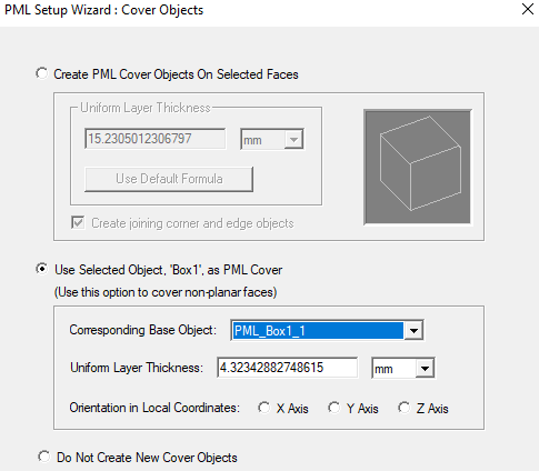
- Select Use Selected Object as PML Cover.
- Select the Corresponding Base Object, the object touching the PML, from the pull-down list.
- Type the thickness of each layer in the Uniform Layer Thickness text box. You can assign a variable as the thickness value.
- Select the Orientation in Local Coordinates of the PML object, X, Y or Z axis, the direction of outward propagation, in the relative, or local, coordinate system.
- Under Base Face Radiation Properties, click a radio button to specify one of the following:
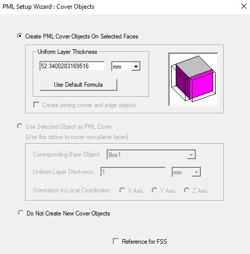
If you selected a surface, the dialog will select Create PML Cover Objects on Selected Faces and disable Use Selected Object as PML Cover. You can also specify whether to Do Not Create New Cover Objects and designate whether a selected surface is used as Reference for FSS, that is, as a Frequency Selective Surface - this surface becomes the input surface for calculations of the reflection/transmission coefficients. The other radiating surface automatically becomes output. Only one FSS can be defined in a given model. Using the Incident Field option together with Reference for FSS is advantageous for highly reflective and resonant structures. Reflection/Transmission coefficients for FSS designs can be viewed in the solution data panel as S-parameters or you can create an S-parameter report.
If you check Reference for Frequency Selective Surface (FSS), the PML objects will stay visible.
- Click Next.
If the selected object does not have a PML prefixed, you will see a dialog asking you to OK a name change. Clicking Next creates a PML cover object, but not a PML boundary.
- Specify how the PML terminates by selecting one of the following:
- PML Objects Accept Free Radiation if the PML terminates in free space.
- Enter the lowest frequency in the frequency range you are solving for in the Min Frequency text box.
- PML Objects Continue Guided Waves if the PML terminates in a transmission line.
- Specify the propagation constant at the minimum frequency.
- Specify the minimum distance between the PML and the radiating body in the Minimum Radiating Distance text box. You may choose to let HFSS calculate the value by clicking Use Default Formula.The default distance is based on the extent of base object geometry.
The PML material characteristics depend on the cumulative effect of their near fields at the location of the PML surfaces.
- Click Next.
If Ansys Electronics Desktop calculates the appropriate PML material based on the settings you specified and the material of the base object, and assigns this material to the PML.
A summary dialog box appears, enabling you to modify the settings you specified.
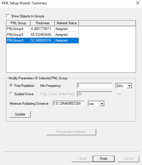
- Click Finish.
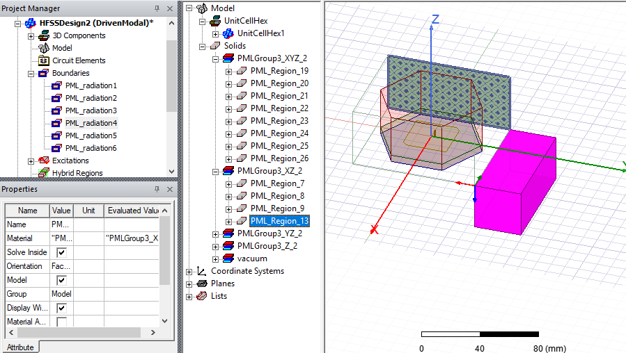
You can Fit the View to see the newly created PML boundaries in the Project tree and the PML groups and objects in the History tree. Selecting the boundaries or objects lets you view them in the Modeler window.