
Assigning Circuit Ports
Circuit Ports in HFSS are equivalent to those in HFSS 3D Layout. These ports provide major benefits for HFSS:
- Good low frequency accuracy (Hz range)
- Good for multi-physics work flows as there is no restriction about being planar
- For designs with only lumped ports or a combination of lumped and circuit ports, the Advanced Solution Setup, Options tab includes an option to use Enhanced low frequency accuracy.
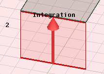
Circuit ports can be thought of as Lumped Ports assigned to a pair of edges. In a driven modal solution, the integration line for the circuit port will be a vector from second edge to the first edge. In the driven terminal problem, the two edges are populated as terminal and reference under circuit port. Deleting either edge will delete the circuit port. You can create circuit ports, translate between circuit ports and lumped ports, and include circuit ports in N-port circuit elements. They are treated exactly as lumped ports.
If you change the solution type between driven modal and driven terminal, the integration line will be converted to terminal and reference under circuit port and vice versa.
Addition, deletion, modification of circuit ports will invalidate solutions. Editing the impedance will invalidate. Changing or deleting the assignment will invalidate.
To assign a Circuit Port:
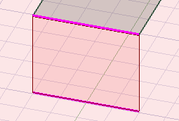
- Select two edges in the modeler window. The order of selection is significant. For a driven modal design, an integration line will go from the second edge to the first edge. For a driven terminal design, the first edge will be assigned a terminal, and the second edge will be assigned a reference.
- Right-click the Excitations Icon in the Project Manager and select Assign> Port>Circuit Port... You can also use the HFSS toolbar menu to select Excitations> Assign>Port> Circuit Port..., or right-click in the Modeler window and click Assign Excitation>Port> Circuit Port....
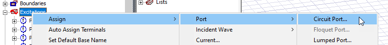
The Circuit Port: General dialog box appears.
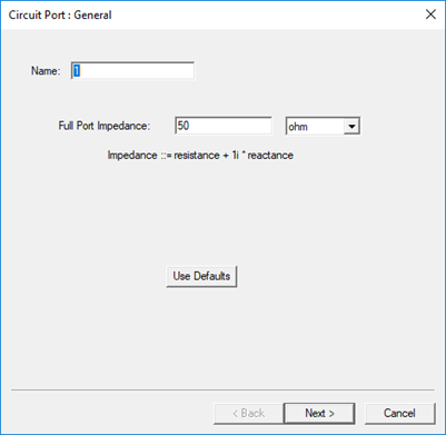
- You can set the Full Port Impedance. Click Next to view the Port Processing tab. These are slightly different for Modal and Terminal solutions.
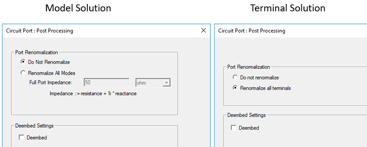
For Modal solutions, the default is Do Not Normalize, but you can choose Renormalize All Modes and specify the Full Port Impedance. For Terminal solutions, the default is Renormalize all terminals. You can also enable Deembed.
- Click Finish.
For Terminal solutions, the History Tree will show the Circuit Port with Terminal and Reference. Selecting the Circuit Port highlights both edges in the Modeler window. Selecting the Terminal or the Reference highlights the associated edge. Terminal is assigned to the first edge selected, and the reference is assigned to the second edge selected. The renormalization impedance belongs to the terminals. Terminal and reference from the circuit port cannot be added to or deleted from the circuit port; exactly one terminal and one reference is required by the circuit port. However, you can reassign terminal and reference independently. Reassigning a circuit port means that its assignment is then populated into the terminal reference.
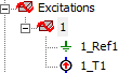
For Modal solutions, selecting the Circuit port in the Project Manager highlights both edges and shows the integration line from the second edge selected to the first edge selected.
When you create circuit ports, you can do the following:
Swap Assignment
Right click on the Circuit Port and click Swap Assignment to swap the direction of an integration line or a terminal reference assignment.
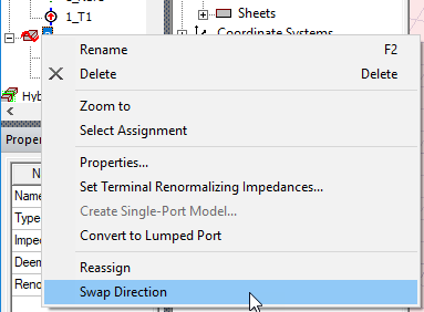
Create a Circuit Element from a Circuit Port
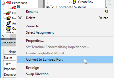
Convert a Circuit Port to a Lumped Port
Select a circuit port, right-click and select Convert to Lumped Port from the short-cut menu.
For driven modal solutions:
- If the two edges are on the same face, the lumped port will be assigned to that face, and the integration line is preserved.
- If the two edges are not on the same face but on the same plane, then a sheet will be created, and the lumped port is assigned to that sheet.
- Otherwise, the conversion fails.
For terminal solutions:
- The terminal is transferred to the lumped port.
- The lumped port face determination is similar to driven modal using the edges from the terminal and the reference.
Convert a Lumped Port to a Circuit Port
Select a lumped port, right click and select Convert to Lumped Port.
For driven modal solutions:
- The integration line is preserved
- If the integration line is defined by two end points on edges, the two edges are the assignment of the circuit port.
- Otherwise, the conversion fails.
For driven terminal solutions:
- The terminal is transferred to the circuit port.
The reference edge is determined by the terminal assignment and the lumped port face assignment. An edge touching a conductor from the face, and not touching the terminal will be the reference edge.