
Padstack Settings
The Edit Padstack Definition window allows you to change the settings for a new or existing padstack.
For more information about adding and editing padstacks, see: Modifying Padstacks.
To access the Edit Padstack Definition window:
- Select the Padstack Editor tab to view the Padstack Editor.
- Select a padstack from the list of padstacks and perform one of the following actions:
- Right-click the padstack and select Edit Padstack, or
- Click the Edit Padstack button.
The Edit Padstack Definition window appears.
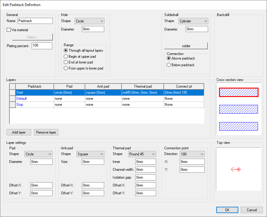
This window contains the following areas for changing settings:
- General – allows you to set a padstack name, via material, and plating percentage.
- Hole – allows you to set a hole shape, dimensions, and range (depth). The dimensions available for editing depend on the shape of the hole.
- Solderball – allows you to set a solderball shape, dimensions, material (default: solder), and connection point (above or below the padstack). The dimensions available for editing depend on the shape of the solderball.
- Backdrill – [[???]]
- Layers – a list of layers in the padstack. You can add or remove a layer using an appropriate buttons, or change a layer's settings in the Layer Settings area below.
- Layer Settings – activated only when a layer is selected in the Layers list. See: Pad, Antipad, Thermal Pad, and Connection Point below.
Additionally, it displays the following visualizations:
- Cross Section View – displays all definition layers and their pads from a side view. Layers selected in the Layers list are highlighted in red. Hovering the cursor over a layer displays its name as a tooltip.
- Top View – displays the pads of selected layers from a top down perspective.
Pad Settings
Pad settings vary based on the shape of pad chosen.
Pad shape choices are:
- None – no pad.
- Circle – specify the diameter, offset x, and offset y.
- Square – specify the size, offset x, and offset y.
- Rectangle – specify the x size, y size, offset x, and offset y.
- Oval – specify the x size, y size, corner radius, offset x, and offset y.
- Bullet – specify the x size, y size, corner radius, offset x, and offset y.
- N-Sided Polygon – specify the size, number of sides, offset x, and offset y.
- Polygon – specify the shape, offset x, and offset y. See: Polygon Editor.
Antipad Settings
Antipad settings vary based on the shape of antipad chosen.
Antipad shape choices are:
- None – no antipad.
- Circle – specify the diameter, offset x, and offset y.
- Square – specify the size, offset x, and offset y.
- Rectangle – specify the x size, y size, offset x, and offset y.
- Oval – specify the x size, y size, corner radius, offset x, and offset y.
- Bullet – specify the x size, y size, corner radius, offset x, and offset y.
- N-Sided Polygon – specify the size, number of sides, offset x, and offset y.
- Polygon – specify the shape, offset x, and offset y. See: Polygon Editor.
Thermal Pad Settings
Thermal pad settings vary based on the shape of thermal pad chosen.
Thermal pad shape choices are:
- None – no thermal pad.
- Polygon – specify the shape, offset x, and offset y. See: Polygon Editor.
- Round45 – specify the inner size, channel width, isolation gap, offset x, and offset y.
- Round90 – specify the inner size, channel width, isolation gap, offset x, and offset y.
- Square45 – specify the inner size, channel width, isolation gap, offset x, and offset y.
- Square90 – specify the inner size, channel width, isolation gap, offset x, and offset y.
Connection Point Settings
For the Connection Point, select a Direction.
- None – No direction.
- Any – specify x and y, for any direction.
- [# in Degrees] – specify x and y.