
The T Model
To begin, let's assume that we have N separate nets (independent electrically connected paths) and that each net has exactly one source and sink. Later we will expand the discussion to consider nets with multiple sources.
The most commonly used equivalent circuit model is the "T" model. It is used when the number of lumps requested is 1. It consists of a grounded "shunt" element (XY1) representing the capacitance matrix and a pair of "series" elements (XZhalf1 and XZhalf2) representing the inductance and resistance matrices. Note that we are assuming that you have actually solved for both sets of matrices-if not, then the model will be simplified further. We postpone discussing these special cases to a later section.
All three subcircuits are contained within a single top-level subcircuit. The terminals of the top-level subcircuit are nodes 1 through 2N. Nodes 1 to N correspond to source terminals and nodes to correspond to the sink terminals. To provide connection points between the internal subcircuits, the top-level subcircuit has a set of internal nodes (nodes 2N+1 through 3N.)
The T model is shown below.
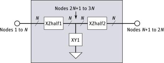
The "T" model is used to represent single-lump equivalent circuits. The gray box in the figure represents the top-level subcircuit. It contains 3 lower-level subcircuit instances. The bold lines represent N-wire bundles or "buses" of wires.