
Single-Source Conductors
If all conductors have just one source terminal and one sink terminal, the system creates a balanced circuit to model the transmission structure — that is, a circuit whose impedance is the same regardless of the direction of current flow. For instance, a two-conductor transmission structure is shown below. Each conductor has a single source terminal through which current flows.

The circuit parameter matrices for this model are:

In the equivalent circuit for this structure, the negative of the mutual capacitance (C12) is used directly as a circuit element. The self-capacitances of each conductor (C11, C22) are used to compute the capacitances between the conductor and ground (C10, C20).
C10 = C11 + C12
C20 = C22 + C12
To create a balanced circuit, each inductance or resistance matrix entry is divided into two series inductors or resistors and placed in the circuit as shown in the following figure:
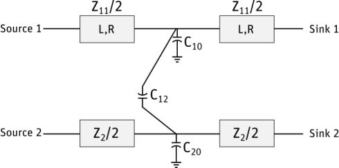
All sinks on a conductor are considered to be connected to each other. Sinks on different conductors are independent.