
The Djordjevic-Sarkar Model
The Djordjevic-Sarkar model is a causal, frequency-dependent dielectric model developed specifically to model the FR-4 epoxy resin material used commonly in printed circuit boards. It is also useful for many other low-loss insulator materials. The formula for the complex permittivity in this model is given by Formula One (1):

Here,  denotes the high-frequency (or optical) limit of the relative
permittivity and
denotes the high-frequency (or optical) limit of the relative
permittivity and  is the difference between the low-frequency (DC limit) of the relative
permittivity and
is the difference between the low-frequency (DC limit) of the relative
permittivity and  .
.
 is the DC conductivity (typically zero for low-loss dielectric materials). The model has lower and upper "corner frequencies"
  and
and  respectively, which are described further below. All of these parameters are real-valued, and are computed for you from the material measurement data you provide.
The effective relative permittivity and conductivity for the Djordjevic-Sarkar model can be derived from the real and imaginary parts of Equation One (1) above.
Equation Two (2):

Equation Three (3):

The effective loss tangent is derived from the ratio of these:

The frequency-dependent behavior of the relative permittivity and loss tangent are illustrated in the following figure. The frequency axis in this figure is shown on a logarithmic scale.
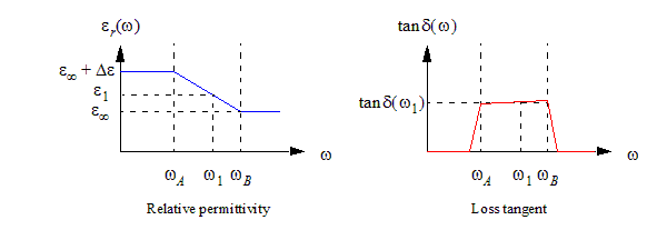
Some important points to note about these curves are:
- The low frequency relative permittivity is always higher than the optical permittivity.
- The relative permittivity decreases almost linearly (on a logarithmic frequency scale) between the two corner frequencies. Above and below this frequency range, it is essentially constant.
- The slope of the permittivity in the linear region is proportional to the loss tangent: a higher loss tangent results in a more rapid decrease of the permittivity.
- The loss tangent is nearly constant between the two corner frequencies. If the DC conductivity is zero, it rapidly decreases to zero outside this frequency range (If the DC conductivity is non-zero, then the loss tangent becomes infinite at DC).
Suppose that the relative permittivity  and loss tangent
  are given at a frequency
  lying between the corner frequencies. Because the loss tangent determines the slope of the line, and the relative permittivity defines a point on the line, the line is completely determined by a single measurement. The only remaining parameters to be decided are the corner frequencies.
The upper corner frequency has not been observed in practice, and so it is set to a very high value ( ) The lower corner frequency will be determined
by the DC permittivity, at the point where the flat DC part of the permittivity
curve meets the linear part. If the user does not provide the DC permittivity,
the software will pick a value such that the lower corner frequency is
on the order of 10 krad/s.
) The lower corner frequency will be determined
by the DC permittivity, at the point where the flat DC part of the permittivity
curve meets the linear part. If the user does not provide the DC permittivity,
the software will pick a value such that the lower corner frequency is
on the order of 10 krad/s.
References
[1] A. R. Djordjevic, R. D. Biljic, V. D. Likar-Smiljanic and T. K. Sarkar, "Wideband Frequency-Domain Characterization of FR-4 and Time-Domain Causality," IEEE Trans. on Electromagnetic Compatibility, Nov. 2001, p. 662.