Convection
Use a Convection boundary to simulate the transfer of heat between object faces and the surrounding environment.
You can assign convection boundaries to the following entities:
- Faces of solid or shell objects
- Objects (solid or shell): Assigning convection to an object is equivalent to assigning convection to all faces of the object.
The convective heat transfer is calculated based on the difference between the surface temperature at the convection faces and the specified ambient temperature, and on the convection film coefficient (also referred to as the heat transfer coefficient). The following film coefficient options are available:
- A uniform, time-dependent, or temperature-dependent film coefficient that you specify.
- For both steady-state and transient thermal solutions: You can specify a temperature-dependent film coefficient. To do so, create a piecewise linear (pwl) dataset to define the coefficient versus temperature values.
- For transient solutions: You can specify a time-dependent uniform film coefficient. Do so by creating a piecewise linear (pwl or pwl_periodic) dataset or a piecewise constant (pwc) dataset to define coefficient versus time values.
- Non-uniform film coefficients that are imported from a linked Icepak design. The Icepak solution takes into account the gas or liquid surrounding the convection faces, the orientation of the faces, and the natural or forced convective flow of the fluid.
The ambient temperature can be defined globally (as a design variable) or specified individually for each convection boundary you assign. Additionally, for transient solutions, you can vary the ambient temperature with time by creating a piecewise linear (pwl or pwl_periodic) dataset or a piecewise constant (pwc) dataset to define the time-dependent temperature values. Please see the Ambient Temperature Guidelines topic for important considerations in defining this value. Note that heat can flow in either direction, from the object to the ambient environment or from the ambient environment to the object, depending on which is hotter.
How to Assign a Convection Boundary:
- Select one or more objects or faces.
- It is often inappropriate to assign convection to an entire object. The reason is that internal faces and those in contact with adjacent objects should not transfer heat via convection; they are not exposed to the ambient environment. Similarly, faces to which other thermal boundaries or excitations are applied (such as Heat Flux) are often not exposed to the ambient environment. The thermal boundary or excitation may represent an adjacent object that is not actually included in the model geometry. In such cases, assign convection to the appropriate individual faces rather than the object.
- You cannot assign a convection boundary to the same face to which thermal contact has been assigned nor to a face that fully or partially overlaps an adjacent thermal contact face. An error message will be produced if you attempt to do so. When a face that is exposed to the ambient environment is in contact with an adjacent part, and contact is assigned where they meet to account for thermal resistance, imprint the smaller part onto the larger one. This operation splits the portion of the face where the parts overlap from the rest of the face. An example is the semiconductor mounting face of a heat sink. Imprint the semiconductor onto the heat sink, which creates two faces from the original one. Then, assign convection only to the exposed portion of the mounting face. (Also, see Assigning a Boundary or Excitation to a Portion of a Face.)
- In certain cases, it is acceptable to assign convection to a body or face that contacts one or more adjacent parts. Specifically, if all the involved objects are in default bonded contact (without thermal resistance), the portions of faces where the objects overlap each other will automatically be excluded from any convection boundaries. In such cases, you could assign convection to an object (such as a circuit board) and the areas where all of the adjacent components (such as capacitors, resistors, and semiconductors) that are bonded to the board will automatically be filtered out of the convection boundary. However, be aware that this automatic filtering of face-overlap areas does not occur for user-defined thermal contact assignments (see previous bullet). It only works for touching objects for which you have not assigned contact to account for thermal resistance.
- For single-face shell objects, assigning convection to the object is equivalent to assigning convection to the face .
- Access the Convection dialog box using one of the following three methods:
- Using the menu bar, click Mechanical > Boundaries > Assign > Convection.
- Right-click Boundary in the Project Manager and choose Assign > Convection from the shortcut menu.
- Right-click in the Modeler window, or right-click a select object in the History Tree, and choose Assign Boundary > Convection.
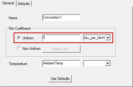
- Select one of the following Film Coefficient types:
- Uniform: A consistent film coefficient definition will be used for all selected faces. The value can be numeric, a variable, or an expression (including constants or variables and operators), or it can be temperature-dependent (using a piecewise linear dataset reference). Additionally, for transient thermal solutions, the value can be time-dependent, using a piecewise linear (pwl) or piecewise constant (pwc) dataset reference.
- For a temperature-dependent film coefficient, reference a dataset (for example, pwl(HTC1,Temperature).
- For a time-dependent film coefficient, reference a dataset (for example, pwc(HTC1,Time).
- Non-Uniform: Film coefficient values will be imported from an Icepak solution. In this case, values are assigned on an individual element face basis and can vary along each of the selected object faces.
- Optionally, specify an alternative value for the ambient Temperature and choose the desired temperature Units from the adjacent drop-down menu.
- The default temperature is the variable, AmbientTemp, which is a global design setting with a default value of 20°C. The procedure for defining the global ambient temperature is given in step 7 below. You cannot alter design settings while the Convection dialog box is still open.
- Refer to the Ambient Temperature Guidelines topic for important information concerning ambient temperature values. When importing convection film coefficients from Icepak, it is especially important that you specify the ambient temperature appropriately.
- Optionally, change the Name of the boundary. The default name is Convectionx, where x is a number that increments for each convection boundary that you assign.
- Click OK to assign the boundary.
- If you are using the AmbientTemp variable for applied convection boundaries and wish to verify or change the value, complete the following procedure:
- Access the Mechanical Design Settings dialog box using one of the following two methods:
- Using the menu bar, click Mechanical > Design Settings.
- Right-click the thermal design heading in the Project Manager [MechanicalDesignx (Thermal), by default]. Then, choose Design Settings from the shortcut menu.
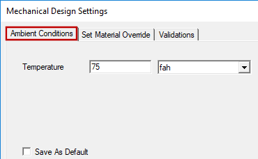
- In the Ambient Conditions tab, specify the desired ambient Temperature value and use the adjacent drop-down menu to choose the Units.
- Click OK.
Specify a suitable Uniform Film Coefficient value and choose the desired Units from the adjacent drop-down menu.
Alternatively:
See the topics, Using Datasets to Define Transient Parameters and Piecewise Constant (pwc) Datasets for more information.
Film coefficients vary widely depending on the ambient environment material, whether that material is gaseous or liquid, the orientation of the faces (for natural convection), and the velocity of the gas or fluid along the solid object faces. For forced convection (using a fan or pump), fluid velocity, and therefore the film coefficients, are significantly higher than for natural convection (driven solely by the buoyancy of the ambient medium). The orientation of an object effects natural convection. Vertical faces tend to convect more heat than horizontal ones because horizontal faces obstruct natural convective flow, and the fluid velocities are typically higher along vertical faces.
Anodization of a material (common for aluminum heat sinks) significantly enhances radiative heat transfer, but it does not affect the convective film coefficient.
Imported film coefficients can be positive or negative. For convective cooling, positive values represent heat flowing from the warmer object faces into the cooler surrounding environment (typically air). When radiation effects are included in the Icepak solution, faces that are located near a heat source may receive radiative heat flow that is greater than the heat flow dissipated into the surrounding environment by convection. This phenomenon results in negative film coefficients locally. Even though mechanical-thermal solutions don't directly handle radiation currently, the imported coefficients from an Icepak solution, with radiation enabled, indirectly account for the radiation effects in the mechanical-thermal solution.
Follow the procedure, How to Setup the Icepak Link, in the Setup Link subtopic before continuing to step 4 of this procedure.
You can specify a numeric Temperature value (along with its units), a user-defined variable, or an expression (consisting of constants, variables, and mathematical operators). For transient thermal solutions, you can specify a dataset reference to vary the temperature with time. Since any user-defined value or dataset overrides the global AmbientTemp value, you can specify a unique temperature for each assigned convection boundary, as needed.
Refer to the topics, Using Datasets to Define Transient Parameters and Piecewise Constant (pwc) Datasets for more information oun using datasets.
The assigned convection appears under Boundary in the Project Manager: