
When to Use Impedance Boundaries in 2D
A typical situation where impedance boundaries can be used to reduce the complexity of a model is shown below. Suppose you want to compute eddy current losses in the conductor next to the current source shown below on the left. If the source carries AC current at a frequency of 1 MHz, the skin depth in the conductor is 6.6 x 10⁻⁵ meters. This is several orders of magnitude smaller than the conductor’s thickness. Since the conductor where currents are induced is also relatively far away from the current source, an impedance boundary can be used to model the induced currents — as shown on the right:
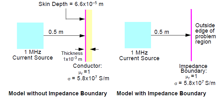
The conductor must be excluded from the model by making it a perfect conductor. The outside boundary of the model is moved to the inside surface of the conductor. This outside surface is defined as an impedance boundary, using the conductivity and permeability specified previously. Since the simulator does not have to actually compute a solution inside the conductor, the field solution is computed more quickly and uses less memory. After solving, you can compute the ohmic loss for the surface using the solution calculator and plot the loss density on the boundary.
Related Topics
Assigning an Impedance Boundary for the 2D Eddy Current Solver