
Permeability Computation for 3D Eddy Current T-W Solutions
For projects with materials whose permeability is nonlinear, setting the permeability link in a 3D Eddy Current T-W design enables it to use the permeability data calculated in a source 3D magnetostatic design, whose matrix/permeability computation setting is Apparent (refer to Inductance Type Tab Settings for Magnetostatic Solutions). In this scenario, the nonlinear analysis is only performed in the 3D magnetostatic source design. In the 3D Eddy Current target design, the nonlinear material is treated as linear material using the “frozen” permeability data from the source design. The target design will be solved based on the mesh and permeability data imported from the source design. Small signal analysis is a typical application for this feature as the operating point in the B-H curve does not change significantly from the static solution to the harmonic solution in the target Eddy Current design.
The permeability link option can also serve as the link if incremental permeability is desired in Eddy Current solutions by setting the matrix/permeability computation as Incremental in the source design settings (refer to Matrix/Permeability Computation Tab Settings for Magnetostatic Solutions).
Prerequisites
- Source design - Maxwell 3D Magnetostatic
- Target design - Maxwell 3D Eddy Current
- The geometry of the source and target designs must be identical.
To set up and use the precomputed permeability link for projects with nonlinear material:
-
Create a 3D Magnetostatic source design using nonlinear material.
Optionally, select the objects to link the permeability by right-clicking Excitations > Set Permeability Computation. By default, all objects with nonlinear BH curve material, including soft magnets and nonlinear permanent magnets, are selected: - Solve the 3D Magnetostatic design.
- Create a 3D Eddy Current target design, whose geometry and materials are identical to the source magnetostatic design.
-
On the Eddy Current Solve Setup window's Solver tab, select Use precomputed permeability data to use the permeability data that has been frozen from a previously solved 3D magnetostatic source design. Selecting this option enables the Setup Link button, and the Setup Link window opens, allowing you to specify the 3D magnetostatic source project, design, and solution containing the desired information. By default, the Setup Link window opens on the General tab with only the Use This Project radio button selected.
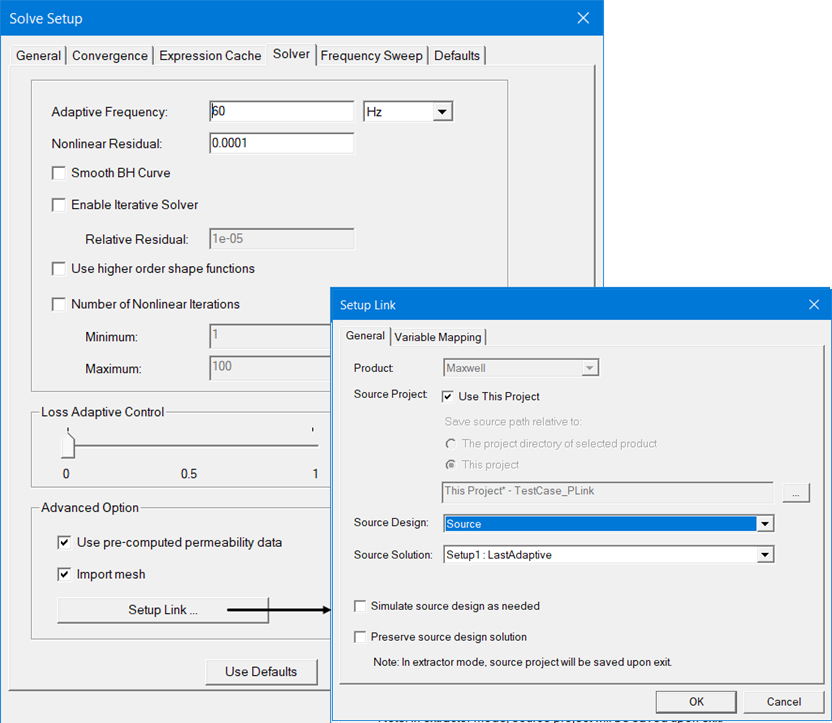
If the Import Mesh option is also selected, the permeability link is performed element-by-element, and adaptive mesh refinement is not allowed in the target design. Otherwise, an object-based link between the source and target designs is considered, and independent meshes and adaptive refinement are allowed in the two designs.
Note: If a link had previously been set up, the Setup Link dialog opens in View Only mode with all settings disabled. To enable settings, you can select Edit Link.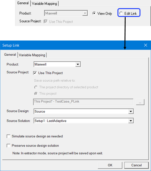
-
On the Setup Link window's General tab, select the source 3D magnetostatic design and solution. The geometry of the source and target designs must be identical.
- To use the current project as the source, check Use This Project. This disables the Save source path relative to: radio buttons and the ellipsis [...] button and its associated text field.
- To specify a source project file other than the current project click the ellipsis [...] button to open a file browser window. When you have selected the project, click the Open button to accept the project file for the setup. You can use the check box to Open as read only.
Use the radio buttons to specify whether to save the source path relative to The project directory of selected product or This project.
- Use the check box to specify whether to Simulate source design as needed.
- Use the check box to specify whether to Preserve source design solution. Note that in the extractor mode, the source project will be saved upon exit. Extractor mode means that the software is opened during the link solely for the purpose of solving.
-
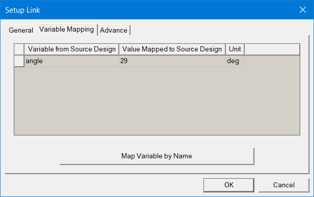
The Variable Mapping tab lets you view any variables contained in the selected Project.
When there are variables in the source design, you can choose to “map” these variables to constant values, expressions, or variables in the target designs. Variable mapping becomes more important when the datalink type requires source and target design to be geometrically identical and the source design is geometrically parameterized.
For linked designs with variables of the same name, you can click Map Variables by Name to automatically map same named variables. If a variable does not have a same named counterpart, it retains its value in the source design.
- Click OK to accept the setup and close the Setup Link dialog and return to the Solve Setup window.
- When you are finished specifying solution settings, click OK to close the Solve Setup dialog box and finalize the solution setup.
-
Solve the target 3D Eddy Current design.
-
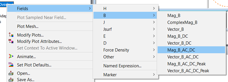
Create field plots of quantities B, H, and J. The DC field result on target design mesh is mapped from source design mesh and fields, and then the plot can generate AC+DC results on target design mesh.
-
The Mag_B_DC, Vector_B_DC is the DC field mapped from magnetostatic source design. They should be close to the field plot in source design, although some differences may exist since the mesh is not the same.
-
The Mag_B_AC_DC, Vector_B_AC_DC is the addition of AC field from eddy-current design and DC field from magnetostaic design.
-
The Mag_B_AC_DC_Peak, Vector_B_AC_DC_Peak is the peak value of AC+DC field among all AC phases.

Related Topics
Matrix/Permeability Tab Computation Settings for 3D Magnetostatic Solutions