
Using the Maxwell Eccentricity Wizard
Note:
The ACT Extensions window and the design wizards it contains are only available for the Windows version of the Ansys Electronics Desktop software. These items are not available when the software is installed on a Linux platform.
You can use the Maxwell Eccentricity wizard to model both 2D and 3D transient designs that have cylindrical rotational motion setup.
Note: If you want to generate a 3D rotational eccentricity motor design from an RMxprt-generated Maxwell 3D design, you must enter Eccentricity 1 in the RMxprt Design Setting window's User Defined Data tab for the RMxprt design before generating the Maxwell 3D design.
- Select View > ACT Extensions to open the ACT Extensions window.
- Click the Wizards button to open the Wizards page, then click Maxwell Eccentricity to load the Maxwell Eccentricity setup page.
- Select the project and design you want to use.Note:
- The Update button synchronizes the project and design selection lists with those currently loaded in the Desktop.
- You can click Exit Wizard to close the eccentricity wizard and return to the wizard start page without executing any changes.
- Depending on whether your design is 2D or 3D, do one of the following:
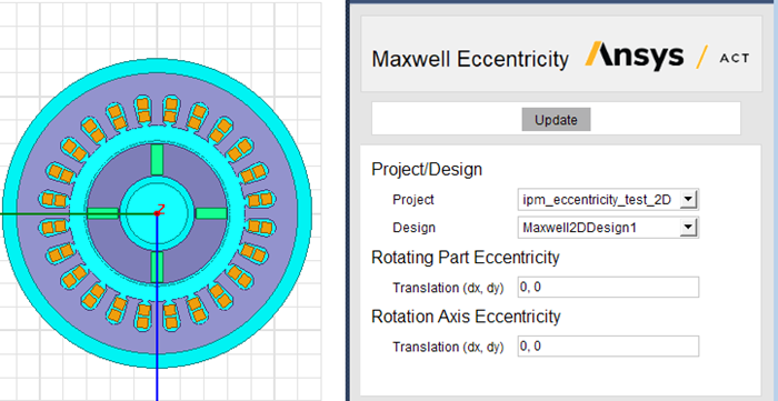
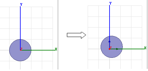
- For a 2D Maxwell project, enter the desired dx and dy translation values to set up the Rotating Part Eccentricity and Rotation Axis Eccentricity. The unit of measure for translation values is the model’s unit, which is set using Modeler > Units.
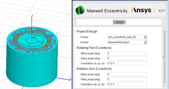
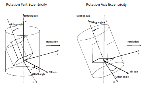
- For a 3D Maxwell project, enter the desired dx, dy , and dz translation values, the offset angle, and the tilting angle for the rotating part eccentricity axis and rotation axis. The unit of measure for translation values is the model’s unit, which is set using Modeler > Units.
- For a 2D Maxwell project, enter the desired dx and dy translation values to set up the Rotating Part Eccentricity and Rotation Axis Eccentricity. The unit of measure for translation values is the model’s unit, which is set using Modeler > Units.
- Click the Finish button at the bottom of the page. The page closes and the wizard adds a new design in the same project, in which the Maxwell geometry has been updated in accordance with the eccentricity setup values you entered, as explained in the sections that follow.
For 2D Designs
- Design variables are created for each of the data entered in the wizard.
- For rotating part eccentricity: _Eccentricity_translation_of_moving_parts
- For rotation axis eccentricity:_Eccentricity_translation_of_rotating_axis
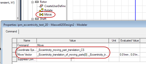
- The moving parts in the design motion setup are shifted according to the data defined for Rotating Part Eccentricity in the Wizard. New coordinate systems are generated as the object coordinate systems for moving parts, according to the same operations.
- The band is translated according to the data defined for Rotation Axis Eccentricity in the wizard.
- The Moving Vector entry in the design’s motion setup is replaced with the new direction (represented by an axis of a new coordinate system) generated according to the data defined for Rotation Axis Eccentricity in the Wizard.
- New design coordinate systems are created.
_Eccentricity_rotating_axis_translation_CS
_Eccentricity_moving_part_translation_CS
_Eccentricity_moving_part_CS_<part name> – one for each moving part
Note:- All the above operations of translation, as well as the creation of new coordinate systems, are dependent on the eccentricity design variables.
- You can modify these design variables to adjust the eccentricity.
- The newly added coordinate systems should not be changed manually by the user.
- Using the wizard to modify a design that has already been set up for eccentricity is not recommended.
For 3D Designs
- Design variables are created for each of the data entered in the wizard.
For rotating part eccentricty:
- _Eccentricity_offset_angle_of_moving_parts
- _Eccentricity_translation_of_moving_parts
- _Eccentricity_tilting_angle_of_moving_parts
For rotation axis eccentricity:
- _Eccentricity_offset_angle_of_motion_axis
- _Eccentricity_translation_of_motion_axis
- _Eccentricity_tilting_angle_of_motion_axis
- The moving parts in the design motion setup are rotated and shifted according to the data defined for Rotating Part Eccentricity in the Wizard. New coordinate systems are generated as the object coordinate systems for moving parts, according to the same operations.
- The band is rotated and translated according to the data defined for Rotation Axis Eccentricity in the wizard.
- The Moving Vector entry in the design’s motion setup is replaced with the new direction (represented by an axis of a new coordinate system) generated according to the data defined for Rotation Axis Eccentricity in the Wizard.
- New design coordinate systems are created.
For the motion moving vector:
- _Eccentricity_motion_axis_CS
- _Eccentricity_motion_axis_tilting_axis_CS
For the moving parts:
- _Eccentricity_moving_part_tilting_axis_CS
- _Eccentricity_moving_part_translation_CS
- _Eccentricity_moving_part_CS_<part name> – one for each moving part
Note:- All the above operations of rotation and translation, as well as the creation of new coordinate systems, are dependent on the eccentricity design variables.
- You can modify these design variables to adjust the eccentricity.
- The newly added coordinate systems should not be changed manually by the user.
- Using the wizard to modify a design that has already been set up for eccentricity is not recommended.
Note: When modeling motion eccentricity, the position and direction of the moving objects and/or band are adjusted based on the eccentricity setup. In such cases, all the adjustments are referenced to the original position and direction of the geometry of each object, As a result, after you finish the eccentricity setup and click the Finish button, all the geometries in the design created by the wizard are updated to new positions based on the eccentricity setup. If you want to edit geometry, you should do so in the original design. After editing the geometry, you can then redo the eccentricity setup to create a new design.