
RMxprt Example Part 5: Create Reports and View Output
After you have run an analysis, you can view the solution data.
-
Click RMxprt > Results > Solution Data.
This opens the Solutions window with the Performance tab selected, and the FEA Input Data displayed. The Solutions window contains tabs for the following:
- Performance – the Data field in the Performance tab is a drop down menu from which you can select the following:
- FEA Input Data
- Full Load Operation
- Material Consumption
- No Load Operation
- Permanent Magnet
- Rotor Data
- Stator Slot
- Stator Winding
- Steady State Parameters
- Design Sheet – Shows the various design parameter values
- Curves – Selecting the Curves tab lets you view predefined graphs.
- Performance – the Data field in the Performance tab is a drop down menu from which you can select the following:
-
On the Performance tab, select Stator Winding as the Data selection.
Except for some data corresponding to the wire gauge, this data should be the same as the data input in the Stator Winding Properties window. Since automatic design function for the wire gauge is selected in the input, RMxprt calculates the following data:
Wire Diameter (mm):
0.8118 for the diameter of the electromagnetic wire.
Wire Wrap (mm):
0 for the insulation thickness of the electromagnetic wire. Because input wire wrap is 0, RMxprt picks it up from the selected wire library (American wire), but it still 0 based on the wire wrap data in the library.
Stator Slot Fill Factor (%):
61.6599.
- n is the total number of wires per slot (the number of conductors per slot times the number of wires per conductor),
- d2 is the square area of a wire with d being the wire diameter including wire insulation, and
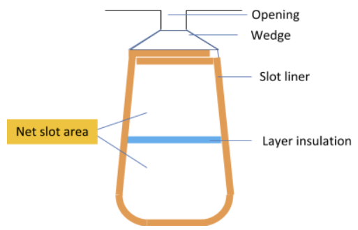
- Snet is the net slot area which is obtained from the gross slot area minus opening area, wedge area, liner area, and layer insulation area, as shown below:
- Now that the Wire Diameter of the electromagnetic wire has been calculated by RMxprt, you can open the Winding Properties window and specify the value.
- For Wire Size, open the Wire Size selection window, select 0.8118 for the electromagnetic wire diameter, which corresponds to 20 for the wire gauge.
- In the slot Wire Wrap field, input 0.08 for the insulation thickness of the electromagnetic wire.
- Click OK to close the properties window.
-
Click RMxprt > Analyze All.
After the second analysis is completed, click RMxprt > Results > Solution Data to view the effect of Wire Wrap Thickness of the electromagnetic wire on Stator Slot Fill Factor.
Wire Diameter (mm):
0.8118.
Wire Wrap Thickness (mm):
0.08.
Stator Slot Fill Factor (%):
75.6182
- In the Solutions window, change the Data selection to Rotor Data.
- In the Solutions window, change the Data selection to Permanent Magnet.
- In the Solutions window, change the Data selection to Steady State Parameters.
- In the Solutions window, change the Data selection to No-Load Operation.
- In the Solutions window, change the Data selection to Full Load Operation.
-
In the Solutions window, select the Design Sheet tab, and scroll down to Winding Arrangement.
This is the layout and the arrangement of the whole two-phase winding of phases A and B, and the short coil pitch factor 5 is taken into account. The 2-phase, 2-layer winding can be arranged in 6 slots as below:
AAABBB
Angle per slot (elec. degrees):
30
Phase-A axis (elec. degrees):
105
First slot center (elec. degrees):
0
-
In the Solutions window with the Design Sheet tab selected, scroll down to Transient FEA Input Data. (This is at the very bottom.)
The following data of the armature winding corresponds to one phase armature winding.
Number of Turns
360
(total number of turns viewed into output terminals)
Parallel Branches
1
Terminal Resistance
4.13
Ohm
(stator winding dc resistance under given operating temperature, 75oC)
End Leakage Inductance
1.3
mH
(of stator winding)
The following data is the equivalent values used to 2D electromagnetic field analyses.
Equivalent Model Depth
65
mm
Equivalent Stator Stacking Factor
0.95
Equivalent Rotor Stacking Factor
0.95
Equivalent Br (residual flux density)
0.87
Tesla
Equivalent Hc (coercive force)
690
kA/m
- In the Solutions window, click the Curves tab.
- Input DC Current vs Speed
- Efficiency vs Speed
- Ratio of air-gap torque to DC current vs Speed
- Output Power vs Speed
- Output Torque vs Speed
- Cogging Torque in Two Teeth
- Induced Coil Voltages at Rated Speed
- Air-Gap Flux Density
- Induced Winding Phase Voltage at Rated Speed
- Winding Currents Under Load
- Phase Voltage Under Load
- For example, click RMxprt > Results > Create RMxprt Report > Rectangular Plot.
- In the Traces tab, for the Current category, select InputDCCurrent, and click the New Report button to generate the report.
- Then for the Torque category select Output Torque and click Add Trace to add the trace to the report. Click Close to close the Report window and display the combined graph.
The electromagnetic wire with Wire Diameter of 0.8118 is equivalent to AWG 20. Stator Slot Fill Factor represents the percentage of occupation of the slot area, i.e. the ratio of the total square sectional area of wires (including Wire Wrap thickness) in a slot to the total slot area less the slot insulation.
The slot fill factor is defined as

where
The Rotor data is displayed.
Here most of the data is the same as input in the Rotor Pole properties window. The only difference is that the Pole Arc Radius replaces Pole Arc Offset and, in addition to MechanicalPole Embrace which is input based on the physical geometry, Electrical Pole Embrace is also given. Electrical Pole Embrace is calculated by the ratio of the average magnetic flux density to the maximum magnetic flux density according to the magnetic flux density distribution along the air-gap.
This part displays the characteristic data of the permanent magnets as well as the Demagnetized Flux Density, the Recoil Residual Flux Density, and the Recoil Coercive Force of the recoil line based on the demagnetization flux density, which are used for finite element analysis when a linear PM characteristics must be specified.
This part displays the Stator Winding Factor, direct- and the quadratic-axis inductances, the Armature Leakage Inductance, the Armature Phase Resistance of the phase winding, the direct- and the quadratic-axis time constants, the ideal Start Torque Constant KT and the Ideal Back EMF Constant KE.
This part displays the magnetic flux densities in the teeth and the yoke of the stator, and the yoke of the rotor. The maximum value among the three magnetic flux densities is 1.59 Tesla, which locates at the knee part of the B-H curve, below the saturation situation.
The mmfs of the teeth and the yoke of the stator, the air-gap, the yoke and the permanent magnet of the rotor are given respectively for half magnetic reluctance path.
The armature reaction mmf due to the armature current is referred to the demagnetization mmf. The magnetic flux leakage coefficient takes into account the part of the magnetic flux in the rotor not linking with the stator. The correction factors for the yoke lengths of the stator and the rotor to calculate the yoke mmfs of the stator and the rotor are also given here.
The no-load revolution speed of this machine is approximately 1946 rpm.
At Rated Output Power (kW):0.550, the following characteristic parameters of the machine are calculated as:
|
Parameters |
Calculated Values |
Units |
|
Average Input Current |
2.93 |
A |
|
(of input current waveform in one voltage period) |
|
|
|
RMS Armature Current |
2.45 |
A |
|
(of phase current waveform in one voltage period) |
|
|
|
Armature Thermal Load |
70.88 |
A2/mm3 |
|
(product of Specific Electric Loading and Armature Current Density |
|
) |
|
Specific Electric Load |
14.71 |
A/mm |
|
(stator current distribution per circumferential length along air-gap) |
|
|
|
Armature Current Density |
4.65 |
A/mm2 |
|
(through cross-sectional area of stator wire) |
|
|
|
Frictional and Wind Loss |
11.42 |
W |
|
(at computed Rated Speed) |
|
|
|
Iron-Core Loss |
20.02 |
W |
|
(due to loss curves of stator and rotor iron-core materials) |
|
|
|
Armature Copper Loss |
47.92 |
W |
|
(stator winding ohmic loss) |
|
|
|
Transistor Loss |
9.14 |
W |
|
(transistor switching loss) |
|
|
|
Diode Loss |
0.60 |
W |
|
(diode power consumption) |
|
|
|
Total Loss |
89.1 |
W |
|
(sum of above losses) |
|
|
|
Output Power |
550 |
W |
|
(the rated operating point is derived based on Output Power) |
|
|
|
Input Power |
639.2 |
W |
|
(product of Rated Voltage and Average Input Current) |
|
|
|
Efficiency |
86.1 |
% |
|
(ratio of Output Power to Input Power) |
|
|
|
Rated Speed |
1557 |
rpm |
|
(at Rated Output Power) |
|
|
|
Rated Torque |
3.37 |
Nm |
|
(at Rated Output Power) |
|
|
|
Locked-Rotor Torque |
32.3 |
Nm |
|
(starting torque at zero revolution speed) |
|
|
|
Locked-Rotor Current |
52.1 |
A |
|
(starting current at zero revolution speed) |
|
|
This displays the Input DC Current Versus Speed graph. If the text is too small to read, you can resize the window. You can view other predefined graphs by selecting from the drop down menu in the Name field.
Selecting the Curves tab lets you view predefined graphs for the following relations:
You can also create additional plots with multiple curves.
This displays the Report dialog box.
Continue to Part 6: Output Design Data.