
RMxprt Example Part 3: Input Design Data
In this part of the example, you provide values for the design and for various parts.
- Click the + button by the RMxprt:Designn icon in the project tree to view the design hierarchy.
- Double-click the icon to view the Machine Properties window.
- Click OK to close the Machine properties window.
- Click the + button by the Machine icon to view the design hierarchy of the motor.
- Double-click the Circuit icon to view the Circuit properties window.
- Click OK to close the circuit properties window.
- Double-click the Stator icon to view the Stator properties window.
- Click OK to close the Stator Properties window.
- Click the + button by the Stator icon to view the hierarchy under the stator.
- Click the slot icon to view the Slot Properties window.
- Click the stator Winding icon to view the winding Properties window.
- Click OK to close the stator Winding Properties window.
- From the menu bar, select Machine > Winding > Connect all coils.
- Double-click the Rotor Icon to view the Rotor Properties window.
- Click OK to close the Rotor Properties window.
- Click the + button beside the Rotor icon to open the project hierarchy under the rotor.
- Double-click the Pole icon to view the Pole Properties window.
- Click OK to close the Pole Properties window.
This displays the Machine icon.
Set the values as indicated below.
|
Machine Type |
Brushless Permanent Magnet DC Motor |
|
Number of Poles |
Set this to 4 |
|
Rotor Position |
Set to Inner Rotor |
|
Frictional Loss |
Set this to 11 Watts (Frictional and windage loss is typically within the range of 1%~3% of the rated output power, in this example, 2% is estimated.) This value is referred to the given Reference Speed. The frictional loss at the computed rated speed will be modified if the computed rated speed is different from the given rated speed. |
|
Windage Loss |
0 |
|
Reference Speed |
Set this to 1500 rpm |
|
Control Type |
DC |
|
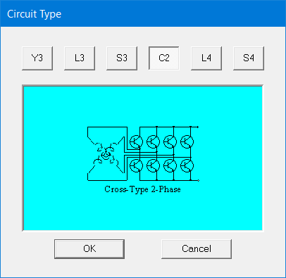
Circuit Type |
Click the C2 button to select and to display the Select Circuit Type window.
Click OK to close the window. |
Set the values as indicated below.
|
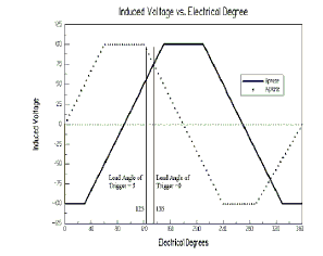
Lead Angle of Trigger |
Set this to 0 degrees to obtain the maximum average emf for the following phase in the trigonal period.
|
|
Trigger Pulse Width |
Set this to 90 degrees |
|
Transistor Drop |
Set this to 2 Volts |
|
Diode Drop |
Set this to 2 Volts |
Set the values as shown below.
|
Outer Diameter |
Set this to 120 mm. |
|
Inner Diameter |
Set this to 75 mm. |
|
Length |
Set this to 65 mm for the length of the Stator iron core. |
|
Stacking Factor |
0.95 |
|
Steel Type |
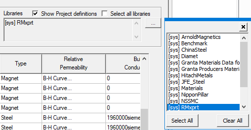
Click on the button to display the Materials window. Select RMxprt library in the Libraries box in the upper right corner of the Materials window: then select M19-24G from the list.
Note: If RMxprt is not listed in the libraries box in the upper right corner of the Materials window, quit the Materials window, click Tools > Configure Libraries, add RMxprt (under materials) and click the Save as Default check box. Then click OK. |
|
Number of Slots |
Set this to 24. |
|
Slot Type |
Select 2 as the Slot type. Click the button on the row cell to display the Select Slot Type window. 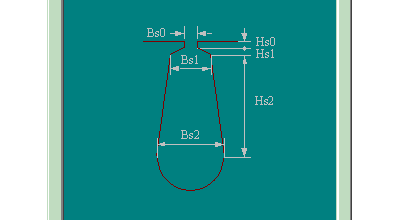
Click OK to close the window. |
|
Skew Width |
Set this to 1. (To skew one slot pitch.) |
Take a moment to look at the Maxwell Design window. If you click the Main tab, you will see two concentric rings that represent the inner and outer diameters you specified. If you click the Winding Editor tab, you see a table of the coils, with columns for Phase, Turns, the In Slots, and the Out Slots. There is also a drawing showing the placement of the 24 slots of the type that you defined here.
Set the values as shown below. Some of the properties will not appear until you disable the Auto Design property in the first row.
|
Auto Design |
Uncheck the box to disable auto design. Close the properties window and open it again. Then set the given values for the slot shapes. |
|
Parallel Tooth |
Uncheck this box. The Tooth Width property becomes invisible. |
|
Tooth Width |
Invisible when Parallel Tooth is unchecked. |
|
Hs0 |
Set to 0.5 mm |
|
Hs1 |
Set to 1.0 mm |
|
Hs2 |
Set to 8.2 mm |
|
Bs0 |
Set to 2.5 mm |
|
Bs1 |
Set to 5.6 mm |
|
Bs2 |
Set to 7.6 mm |
Set the values as shown below.
|
Winding tab |
Winding Layers |
Set this to 2. |
|
|
Winding Type |
"Whole-Coiled." |
|
|
Parallel Branches |
Enter 1 for the number of parallel-connected branches, i.e. the coils in all the slots per phase are in series-connected. |
|
|
Conductors per Slot |
Set this to 60 for the number of conductors per slot, i.e. the number of turns per coil is equal to 30 for double-layer winding. |
|
|
Coil Pitch |
Set this to 5. For this example, full pitch = 24 slots / 4 poles = 6. This example uses short coil pitch, 5, i.e. a coil spans from slot 1 to slot 6. |
|
|
Number of Strands |
Select 1 for the number of strands (or number of wires per conductor). |
|
|
Wire Wrap |
Select 0. This is the total thickness of double side wire insulation. The input value 0 means that RMxprt will automatically check into the wire gauge library for the wrap thickness relevant to the wire gauge. Different manufacturers produce different Wire Wrap Thickness for electromagnetic wire. Typically, Wire Wrap Thickness for electromagnetic wire is 7~10% of Wire Diameter. |
|
|
Wire Size |
Click on the Properties field to display the Wire Size window and select AUTO for automatic design of wire Gauge. Wire Size will be set to 0 in the Wire Size window. This example relies on RMxprt to automatically select the optimum diameter and the gauge code for electromagnetic wire. Close the window. |
|
End/Insulation tab |
Input Half-turn Length |
Uncheck this box. |
|
|
Half Turn Length |
This item is not shown if Input Half Turn Length is unchecked. |
|
|
End Extension (End Adjustment) |
Set this to 0 mm for the linear overhang of the end part of the coil out of the iron core as shown below. In this example, the coil turns immediately at the slot opening, therefore input 0. 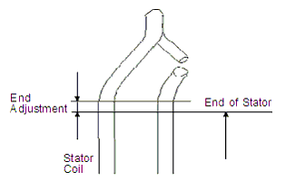
|
|
|
Base Inner Radius |
0 |
|
|
Tip Inner Diameter |
0 |
|
|
End Clearance |
0 |
|
|
Slot Liner |
Set this to 0.3 for the single side thickness of slot insulation. |
|
|
Wedge Thickness |
0 |
|
|
Layer Insulation |
0 |
|
|
Limited Fill Factor |
0.75 (The slot fill factor is the ratio between the cross-sectional area of all conductors in one slot and the entire slot area.) |
The Winding tab in the main window shows all coils connected.
Set the values as shown below.
|
Outer Diameter |
Set this to 74.0 mm. This is the Stator inner diameter - 2* AirGap. |
|
Inner Diameter |
Input 26 mm for the inner diameter of the rotor core. This is also the diameter to match the shaft. |
|
Length |
Input 65 mm for the length of the rotor core. In this example, the lengths of the iron cores of the stator and the rotor are the same. |
|
Steel Type |
Select M19-24G for the material of the silicon-steel sheet for the rotor. In this example, the laminations are punched together on the same sheet; therefore, the material of the silicon-steel sheet and the stacking factors are the same for the stator and the rotor. |
|
Stacking Factor |
Input 0.95. |
|
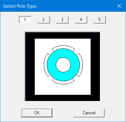
Pole Type |
Select 1. Click on the button on the Pole Type field to display the Select Pole Type window.
Click OK to close the window. |
Set the values as shown below.
|
Embrace |
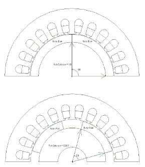
Input 0.7. Embrace of the rotor represents the ratio of the rotor central angle corresponding to the arc length along the rotor surface of an arched permanent-magnetic piece to the rotor central angle corresponding to a rotor pole. In a four-pole machine with an Embrace value of 1, each arched permanent-magnetic piece covers 90 mechanical degrees along the rotor surface. Similarly, with an Embrace value of 0.667 each arched permanent-magnetic piece covers 60 mechanical degrees along the rotor surface, as shown in the figure.
|
|
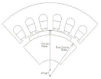
Offset |
Input 0. The arched permanent-magnetic pieces to form the magnets of the rotor might not be concentric with the rotor as shown in the figure. In the electric machines with non-uniform air-gap, there exists an offset between the two centers. RMxprt terms it as Pole Arc Offset. This example uses uniform air-gap; therefore, the offset is set to 0.
|
|
Magnet Type |
Select XG196/96. This permanent-magnetic steel possesses residual flux density 0.96 Tesla, coercive force 690 kA/m, maximum magnetic energy product 183 kJ/m3, and relative recoil magnetic permeability 1.0. |
|
Magnet Thickness |
Input 3.5 mm for the thickness of the permanent-magnetic steel. |
To continue to Part 4 of the example, go to Analyze the Design.