
Permanent Magnet Field Excitations for 2D and 3D Transient and Magnetostatic Solvers
(Maxwell 2D/3D Transient and Magnetostatic Solvers)
Links to demagnetization and magnetization computation source designs can be added as permanent magnet field excitations in target designs. A permanent magnet field excitation can be either object-based (assigned to geometry) or design-based (not assigned to geometry).
To add or edit a permanent magnet field excitation:
The following procedure assumes that a source design, in which either the demagnetization or magnetization operating points computations of the magnet have been modeled, is available for linking.
The target design object on which the Permanent Magnet Field is assigned should have a local coordinate system assigned.
-
This coordinate system must be right-(or left-)handed, the same as in the source design.
-
The target design object should be in the same quadrant of the new local coordinate system as the matching object in the source design.
-
Do one of the following:
- If you are adding a new design-based permanent magnet field excitation, select Maxwell 2D or 3D > Excitations > Assign > Permanent Magnet Field. Alternatively, in the Project Manager you can right-click Excitations to open its context menu, then select Assign > Permanent Magnet Field.
- If you are adding a new object-based permanent magnet field excitation, select one or more objects (magnets) that you wish to include in the permanent magnet field excitation, then either select Maxwell 2D or 3D > Excitations > Assign > Permanent Magnet Field, right-click Excitations in the Project tree to open its context menu and select Assign > Permanent Magnet Field.
- If you are editing an existing permanent magnet field excitation, right-click on the excitation in the project tree and select Properties from the context menu.
-
In the Permanent Magnet Field dialog box, enter (or edit) the Name for the excitation - or accept the default.
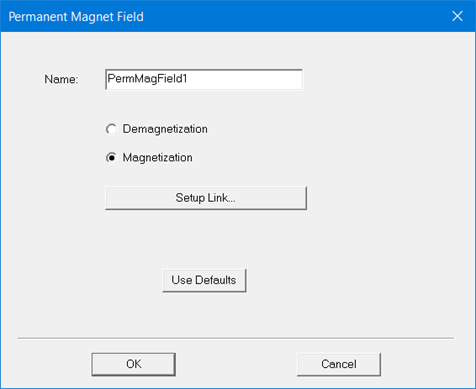
- Depending on how the source design which is to be linked has been configured using Set Demagnetization/Magnetization Computations, choose either Demagnetization or Magnetization for the excitation type, then click Setup Link.
- By default, the Setup
Link dialog opens on the General
tab with only the This project
radio button selected.
Note
If a link had previously been set up, the Setup Link dialog box opens in View Only mode with all settings disabled.
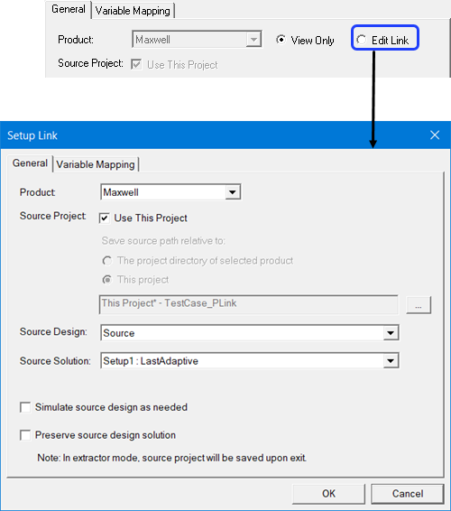
To enable settings, you can select Edit Link.
-
To select a source project do one of the following:
- To use the current project as the source, check Use This Project. This disables the Save source path relative to: radio buttons and the ellipsis [...] button and its associated text field.
-
To specify a source project file other than the current project click the ellipsis [...] button to open a file browser window. When you have selected the project, click the Open button to accept the project file for the setup. You can use the check box to Open as read only.
Use the radio buttons to specify whether to save the source path relative to The project directory of selected product or This project.
-
When you select a source project file, the Source Design and the Source Solution fields are filled in with default values, and their drop-down menus contain any available designs and solutions. You can use the drop-down menus to choose from the available designs and solutions.
The “Default” solution is the product-dependent solution of the first Setup. That is the setup listed first in the source design's project tree (alphanumerical order). A product-specific solution of this setup becomes the default solution. In most products, it is “LastAdaptive.”
- Use the check box to specify whether to Simulate source design as needed.
- Use the check box to specify whether to Preserve source design solution. Note that in the extractor mode, the source project will be saved upon exit. Extractor mode means that the software is opened during the link solely for the purpose of solving.
-
The Variable Mapping tab lets you view any variables contained in the selected project.
When there are variables in the source design, you can choose to “map” these variables to constant values, expressions or variables in the target designs. Variable mapping becomes more important when the datalink type requires source and target design to be geometrically identical and source design is geometrically parameterized.
For linked designs with variables of the same name, you can click Map Variable by Name to automatically map same named variables.
-
For object-based permanent magnet field excitations only, the Object Mapping tab lets you map objects in the target design to objects in the source design.

- Click OK to close the Setup Link dialog box and return to the Permanent Magnet Field dialog box.
- Optionally, the Defaults tab allows you either to save the user-defined data for the excitation as the default for initializing new excitations of this type, or to clear any existing user-defined defaults and revert to standard defaults.
- When finished, click OK to accept the settings and close the dialog box.
Related Topics
Setting Demagnetization/Magnetization Computations for Source Designs