
Partial Simulation for Full Rotational Machine Models
A rotational machine can be simulated by using either a 360 deg full model, or a partial model with matching boundary. Full model simulation has higher memory and time cost than partial model simulation; while partial model would require manual operations to cut the model and assign a matching boundary. The manual cut on the geometry could introduce geometry issues which lead to poor mesh quality near matching boundaries.
Partial simulation for full rotational machine models is designed to combine the benefits of full model simulation and partial model simulations. Without any manual cutting of the geometry, Maxwell can perform partial simulation for full rotational machines.
Background Information
Partial simulation for a full rotational machine model generates and solves a partial mesh on the full model. Instead of a manual cutting of the geometry, this feature allows the mesher to decide where to make the cut. The mesher will also automatically create virtual matching boundaries for the partial mesh.
The following example uses the ipm_2.aedt model in the [install_dir]\Examples\RMxprt\ipm folder to generate a Maxwell 3D model with Total circumferential fractions in created 360 deg geometry on the Symmetry Multiplier tab set to 4.
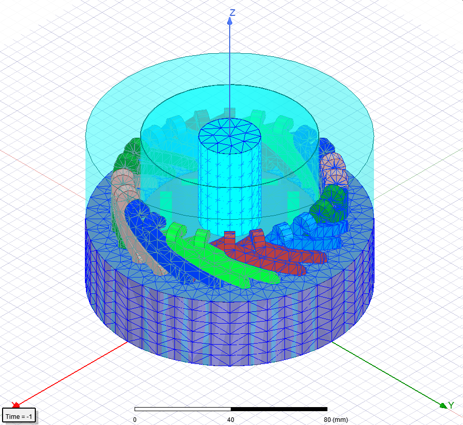
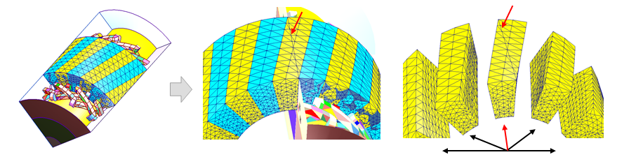
The figure below shows a full mesh on the full ipm_2 model with an element count of 95759:
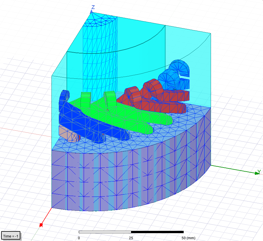
The following figure shows a partial mesh on a manually cut partial model for which the element count is 22194:
The following figure shows a behind-the-scene partial mesh on a full model for which the element count is 20298. Note that the element count for the partial mesh on a full model is comparable to partial mesh on a partial model, for which neither a manual model cut, nor matching boundary assignment is required.
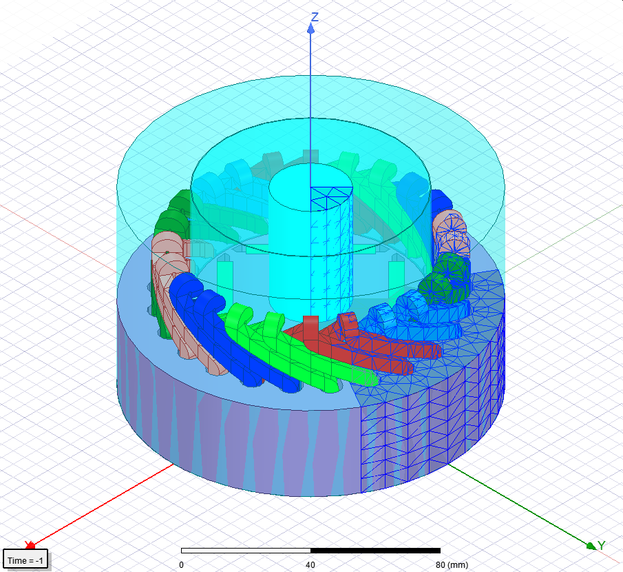
When plotting the partial mesh on the full model, although behind-the-scene mesh only covers part of the model, the mesh plot will be copied and cover the full 360 degree model. Thus, the following model will actually be displayed:
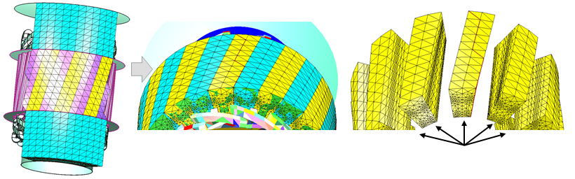
A model with a skewed stator gets even more benefits with partial clone mesh. As shown below, because of the manual cut on the geometry, the skewed model cannot get a perfectly repeatable clone mesh near the matching boundary with partial mesh for a partial model.
On the other hand, with non-planar virtual matching boundary in partial mesh for the full model, identical mesh can be generated for all repeatable geometry patterns.
Workflow for Partial Simulation for a Full Rotational Machine Model
- After solving the RMxprt machine design, create a full rotational Maxwell 3D machine design with 360 deg geometry.
- Select Solve one circumferential fraction in Symmetry Multiplier settings.
- Enter an integer value for the Total circumferential fractions in created 360 deg geometry. For example, if a full model can be cut into a 1/4 partial model and matching boundary can be assign at 0 deg and 90 deg of the model, the integer value entered should be 4.
- Select either Full or Half for Create geometry in axial direction depending on whether the created model is the half model or the full model in axial direction.
- For a rotating machine, the simulation solution is periodic in the circumferential direction. Thus, select either Periodic or Half-periodic for Field in one fraction depending on whether the simulation solution in one fraction is of one period or half period physically.
- Click OK to close the dialog
- Run simulation on the model.