
Coupling Maxwell with Ansys Motion in Workbench
Direct cosimulation between Maxwell and Ansys Motion in Workbench makes possible magnetic latch modeling, which is typically used for modeling magnetic latching structures such as magnetic chargers used by mobile devices. Ansys Motion in Workbench is the primary (controlling) design, while Maxwell serves as the secondary design. During the cosimulation, Motion provides objects position data to Maxwell, then Maxwell feeds force/torque data for these objects back to Motion.
Ansys Motion in Workbench can define the material name, coordinate system, and magnetization direction of a group.
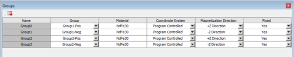
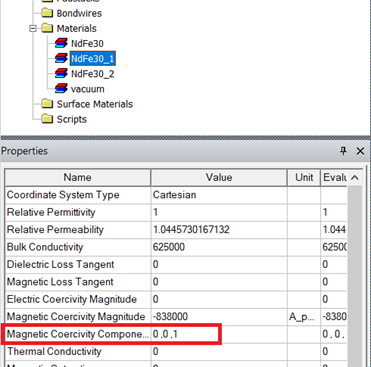
The material name and the magnetization direction are passed to Maxwell. Maxwell creates the materials with the correct Magnetic Coercivity Component, then assign them to the corresponding objects. If the material has a different direction than the system default value, a new clone of the material will be created with a new name adding a number at the end.
The suggested workflow for magnetic latch modeling using cosimulation between Ansys Motion in Workbench and Maxwell is as follows:
-
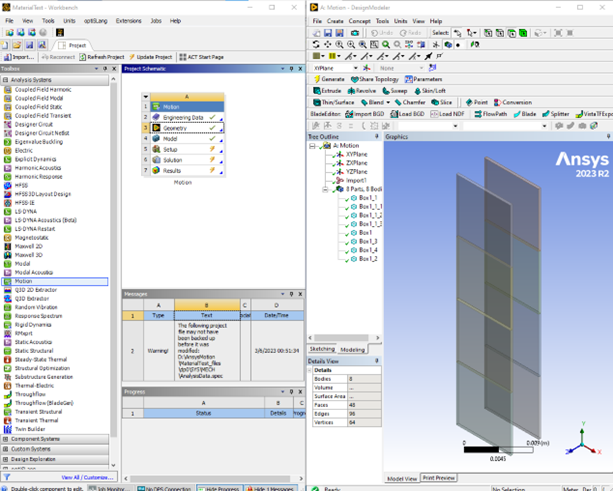
Create a Motion project in Workbench; then draw or import geometry in the design modeler.
-
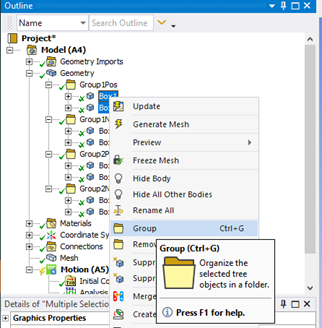
Create groups of objects that are fixed together and have the same material in Motion.
-
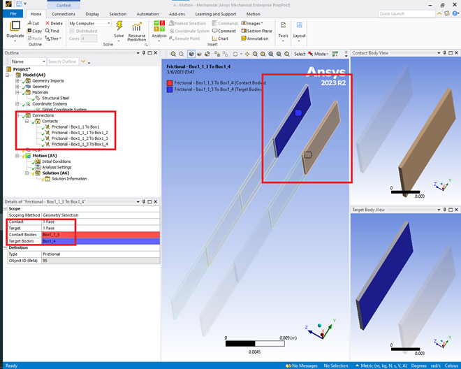
Delete the automatically created contacts and create Contact connections between the faces that will be touching each other.
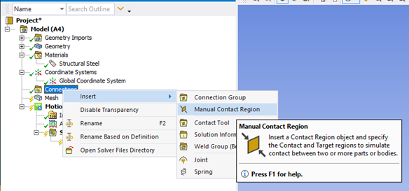
This is an example of creating four contacts between four pair of faces:
-
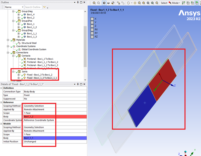
Create Fixed Joints on the groups that move together.
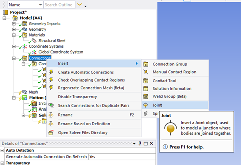
The objects within a group are fixed together by default, so only one Fixed Joint is required to connect two groups:
-
Create a Magnetic Force in Motion.
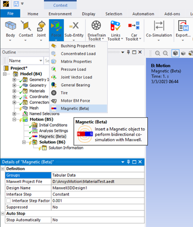
-
Assign the material name and magnetization direction to the groups.
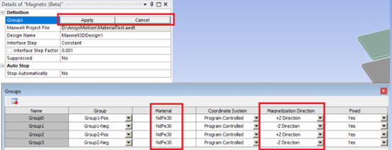
-
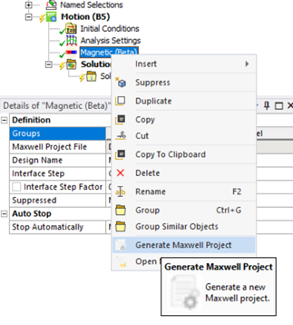
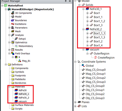
Generate the Maxwell project.
The objects in the groups should be assigned to the corresponding materials.
Related Topics