
Harmonic Force Interpolation in Frequency-Speed Plane
For Electrical Machines
In order to generate the ERP waterfall diagram of electrical machines in Ansys Mechanical Harmonic Response, harmonic force distribution at different rotation speeds from Maxwell solver is provided as excitations of Mechanical. In general, the quality of the ERP diagram depends on the number of speed points that are solved. To reduce the workload in Maxwell, an option is provided to interpolate harmonic force in the frequency-speed plane with a limited number of solved speed points.
In electrical machines, harmonic forces only exist at certain frequencies (harmonics) at a given speed (as shown below):
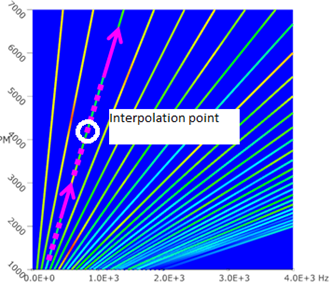
Force components and corresponding frequencies at any given speed can be obtained by interpolation along those lines of harmonics:


where
F : force vector
f : frequency
ω : speed of rotation
k : index of harmonics
i : index of solved speed points
M : total number of solved speed points
To set up the number of interpolation points per segment:
-
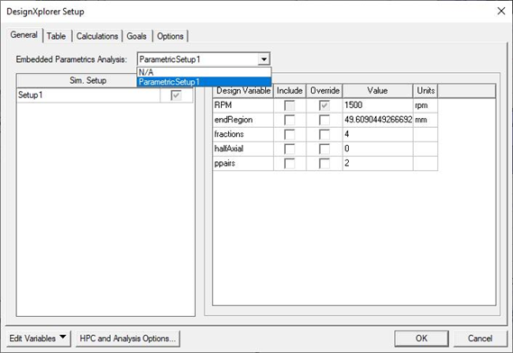
Open the DesignXplorer Setup panel and set Parametric Sweep (RPM sweep) as the Embedded Parametric Analysis.
-
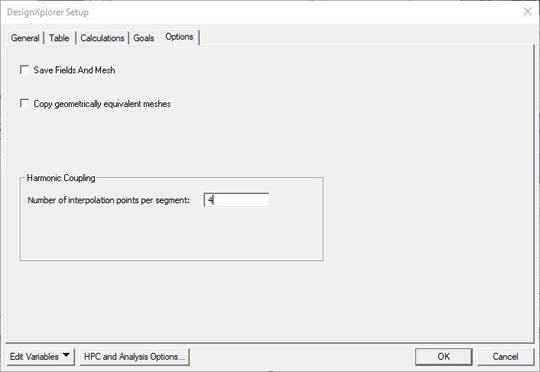
On the Options tab, enter the Number of interpolation points per segment. (This value must be a non-negative integer.)
For Inverter-Fed Motors
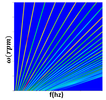
The interpolation scheme described for electrical machinesis valid for harmonics related to mechanical rotation speed of electric machines. When the electric machine is fed from an inverter with a fixed switching frequency, the high-frequency harmonics due to the switching frequency have to be interpolated differently. Below is a typical waterfall phase current for inverter-fed electrical machine:
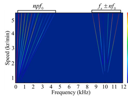
The diagram shows that there are two types of current harmonics: One is the current order harmonics npf0. The other is the switching-frequency sideband harmonics fs ± nf0. The harmonic force resulting from the speed-related part can be interpolated with RPM by using algorithms described for electrical machines. The current harmonics related to switching frequency will generate harmonic force components at frequencies around switching-frequency and its multiples:
f = mfs+ nf0
Where fs is switching frequency, f0 is the mechanical rotating frequency, m and n are integers. In the Maxwell solver, m is calculated by:

Here fmax is the input maximum frequency by user, and n is the number of harmonic distortions.
The harmonic force interpolation scheme for inverted-fed machines is similar to the one described for electrical machines:
-
The speed-frequency lines are constructed at and around switching-frequency and its multiples based on the calculated harmonic force data at specified RPM sweep.
-
Linear interpolation takes place along speed-frequency lines.
In order to distinguish different zones of harmonic force interpolation, the harmonics in the speed-related region is set to a maximum of 50.