
Harmonic Force Interpolation for Inverter-Fed Motors
The interpolation scheme described in Harmonic Force Interpolation in Frequency-Speed Planeis valid for harmonics related to mechanical rotation speed of electric machines. When the electric machine is fed from an inverter with a fixed switching frequency, the high-frequency harmonics due to the switching frequency have to be interpolated differently. Below is a typical waterfall phase current for inverter-fed electrical machine:
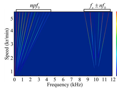
The diagram shows that there are two types of current harmonics: One is the current order harmonics npf0. The other is the switching-frequency sideband harmonics fs ± nf0. The harmonic force resulting from the speed-related part can be interpolated with RPM by using algorithms described in Harmonic Force Interpolation in Frequency-Speed Plane. The current harmonics related to switching frequency will generate harmonic force components at frequencies around switching-frequency and its multiples:
f = mfs+ nf0
Where fs is switching frequency, f0 is the mechanical rotating frequency, m and n are integers. In the Maxwell solver, m is calculated by:

Here fmax is the input maximum frequency by user, and n is the number of harmonic distortions.
The harmonic force interpolation scheme is similar to the one described in Harmonic Force Interpolation in Frequency-Speed Plane:
-
The speed-frequency lines are constructed at and around switching-frequency and its multiples based on the calculated harmonic force data at specified RPM sweep.
-
Linear interpolation takes place along speed-frequency lines.
In order to distinguish different zones of harmonic force interpolation, the harmonics in the speed-related region is set to a maximum of 50.