
HairpinCoil UDP
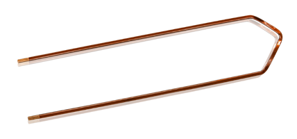
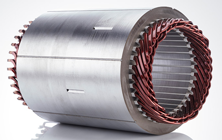
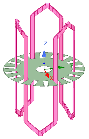
The HairpinCoil UDP is used to create a hairpin-type coil. Hairpin coils are used to make a hairpin winding in a slotted core. All hairpin coils belonging to the same phase are welded in series to perform a hairpin winding.
|
|
|
Hairpin Coil |
Stator with Hairpin Winding |
|
Property |
Description |
|
DiaGap |
Core diameter on gap side, DiaGap < DiaYoke for outer cores. |
|
DiaYoke |
Core diameter on yoke side, DiaYoke < DiaGap for inner cores. |
|
Length |
Core length, 0 for 2D. |
|
Skew |
Skew angle in core length range. |
|
Slots |
Number of slots. |
|
SlotType |
Slot Type: 1 to 7. |
|
Hs0 |
Slot opening height. |
|
Hs1 |
Slot wedge height. |
|
Hs2 |
Slot body height |
|
Bs0 |
Slot opening width |
|
Bs1 |
Slot wedge maximum width |
|
Bs2 |
Slot body bottom width, 0 for parallel teeth |
|
Rs |
Slot body bottom fillet |
|
FilletType |
0: a quarter circle; 1: a tangent
connection, |
|
Layers |
Number of total coil layers in a slot, should be an even number. |
|
CoilPitch |
Coil pitch measured in slots |
|
EndExt |
One-side end extended length |
|
SpanExt/SpanGap |
> 0: axial span extension; = 0: 45° span angle; < 0: negative span gap |
|
SegAngle |
Deviation angle for slot arches (5~15, <5 for true surface) |
|
2ndPitch |
The second coil pitch, the pitch between two conductor sides to be welded |
|
2ndSpanExt/Span Gap |
> 0: axial span extension; = 0: 45° span angle; < 0: negative span gap |
|
WireWidth |
Wire width in slot width direction. |
|
WireThick |
Wire thickness in slot depth direction. |
|
WireRad |
Wire fillet radius, used to calculate equivalent wire size based on wire area. |
|
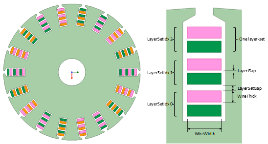
LayerSetGap |
Gap between two layer-sets, one layer-set is two layers of one coil. |
|
LayerSetIdx |
Layer-set index for the location of the coil to be drawn |
|
LayerGap |
Gap between two layers in a layer set |
|
WindingType |
1: whole-coiled (2 coil sets per pole pair) |
|
CoilSetIdx |
0: create 1st coil set; |
|
LenRegion |
Region length, to limit lead length for open coils |
|
InfoCoil |
0: winding; 1: one coil; 100: region |
Parameter Considerations
- Parameter Layers defines the total number of layers, or total number of conductors per slot. The value must be an even number. Two layers related to one coil are referred as one layer-set.
-
For the parameter SpanExt/SpanGap, when its value > 0, it defines the span extension length in axial direction (including span connectors, but not including U-type end tips) .
When the value is 0, the span extension will be automatically derived based on a 45° span slope angle at the inner diameter of the whole winding.
When the value < 0, the minimum span gap between two adjacent coils at the inner diameter of the whole winding will be defined as a negative value based on which the span extension is automatically derived. In this way, all span extensions at different layers will have the same length. -
Parameter 2ndPitch, which defines the second coil pitch (shown below), is the pitch between two coil sides to be welded.
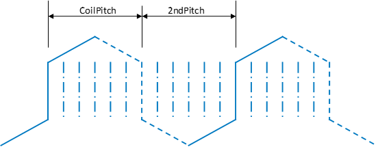
Parameters for CoilPitch and 2ndPitch
For an integer-slot winding, Slots value is a multiple of 2ndPitch plus CoilPitch values. In such a case, the last coil in a coil chain will close the first coil, resulting in a closed coil chain, as shown below.
Closed hairpin-coil chain with 2ndPitch = 3 in an 18-slot core lamination
-
Parameter 2ndSpanExt/SpanGap defines the span extension length for the returning side leg spans, please refer to the SpanExt/SpanGap consideration above.
-
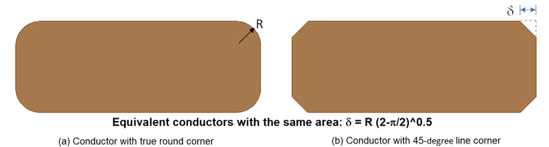
As a good compromise between accuracy and geometrical modeling effort, for 3D models, the UDP will convert the round corner fillets of the conductors’ cross-section to 45-degree chamfers at the corners as shown in (b) of the figure that follows. This conversion is done in such a way that the cross-sectional area of the conductor is maintained. In 2D models, equivalent conductors with 45-degree corner will be used when SegAngle ≥ 5°, and conductors with true round corner will be used when SegAngle < 5°.
- In order to obtain good mesh quality, the UDP will not create wire with wire fillet radius, as shown above, but the effect of wire fillet radius on the wire area will be considered using a scaling factor for both WireWidth and WireThick. The scaling factor k = (WireArea / WireWidth / WidthThick) ^ 0.5, where WireArea is the wire cross-section area considering wire fillet.
- The UDP will get the maximum available rectangular space inside a slot via an optimization process for wire arrangement. The minimum gap between a wire and a rectangle side will be default as 0.3 mm, considered as the thickness of a slot liner insulation. The gap between two layers in one layer-set is the same for all layer-sets. The value is automatically derived from the height of the rectangular space minus total wire thickness and total layer-set gap.
-
WindingType and CoilSetIdx are used for fractional-slot windings only. You do not need to input these values for integer-slot windings. For a fractional-slot winding, the last coil in a coil chain will not close the first coil, and the coil chain will continue to include all coils belong to the same coil set. Finally, the UDP will create an opened coil set. Two lead wires will extend the opened coil set to touch one region end. For whole-coiled windings, since the two coil sets may have different coil arrangement, we need to create two coil sets separately. Parameter CoilSetIdx indicates which coil set is being created. The coil arrangement is based on three-phase windings.
-
For other parameters, refer to LapCoil UDP.