
ECEDCM Model
The ECEDCM model enables you to create a reduced-order model (ROM) of a commutator machine, such as a permanent magnet DC (PMDC) machine, an electrically excited DC machine, or a universal motor, from Maxwell 2D and 3D transient solutions. The symbol of an ECEDCM model element is shown below:
To change the name of the model placed in the Schematic Editor window, double-click the symbol to open its Properties window, and from the Parameter Values tab, enter the new name in the Value field for the DeviceName parameter:
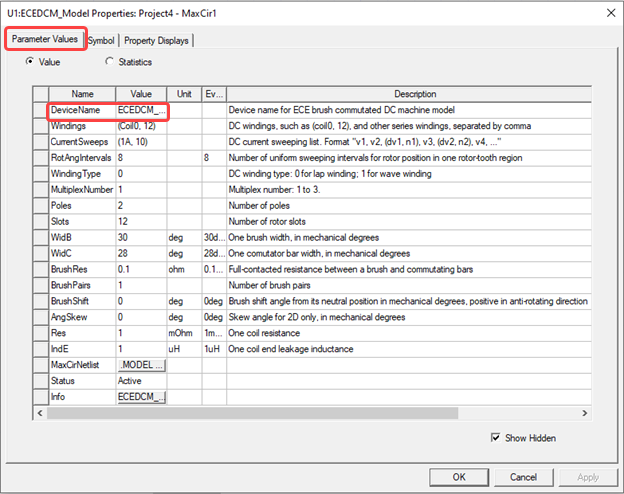
The ECEDCM model contains the following parameters:
- DeviceName – specifies the name of the device model; the default name is ECEDCM_Model1.
- Windings – specifies an armature winding, as well as all other windings connected in series with the armature winding. The armature winding is specified by two parameters inside a pair of parentheses. The first parameter specifies the base coil name, which consists of a non-digit string and an index number of 0 or 1, such as Coil0, or Coil1. The second parameter specifies the number of armature coils.
Other series windings are directly specified with winding names, separated by a comma “,” between any two windings. For example, if a PMDC machine has an armature winding consisting of twelve coils with the base coil name of Coil0, then the armature winding is specified as (Coil0, 12). Windings of a universal motor having eighteen armature coils with base coil name of Coil1 can be specified as (Coil1, 18), Field; here Field is the field winding name. -
CurrentSweeps – specifies input current sweeps for the armature winding and all windings connected in series with the armature winding; see CurrentSweeps for the ECEW model for more details. For a PMDC motor, you need to list 0 and all positive sweeping currents. For a universal motor, you need to list all negative, 0, and positive sweeping currents.
-
RotAngIntervals – specifies the number of uniform sweeping intervals for rotor position in one rotor-slot region. For an eighteen-slot rotor, one rotor-slot region is twenty mechanical degrees. If RotAngIntervals = 8, the sweeping step for rotor position will be 2.5 mechanical degrees.
-
WindingType – specifies armature winding type: 0 for lap winding and 1 for wave winding.
-
MultiplexNumber – specifies the multiplex number: 1 for simplex winding, 2 for duplex winding, and 3 for triplex winding.
-
Poles – specifies the number of poles of the machine.
-
Slots – specifies the number of rotor slots.
-
WidB – specifies one brush width in mechanical degrees.
-
WidC – specifies one commutator bar width in mechanical degrees.
-
BrushRes – specifies full-contacted resistance between a brush and commutator bars.
-
BrushPairs – specifies the number of brush pairs. For a lap winding, the number of brush pairs is always the same as the number of pole pairs. For a wave winding, it could be 1 or the number of pole pairs required to have a periodic circuit.
-
BrushShift – specifies the brush shift angle from its neutral position in mechanical degrees; it is positive in the anti-rotating direction.
-
Res – specifies the resistance of one armature coil.
-
IndE – specifies the end-leakage inductance of one armature coil for 2D.
An ECEDCM model can be used individually to create a ROM of a PMDC machine, a series-excited DC motor, or a universal motor (series-excited AC motor). Combined with an ECEW model that sets up the shunt winding current sweep, this model can also be used to create a ROM of a separate excitation DC machine.
When the winding list in the ECEDCM model includes an armature winding and one or more series windings, the total resistance and the end leakage inductance of all other series windings can be specified in the created Simplorer circuit model via arguments rs and lse, respectively, as shown in the following figure:
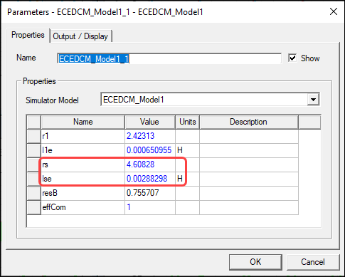
The Simplorer circuit model also includes the effCom argument, which is used to specify the weight of the commutating current effect. The commutating current effect is described below.
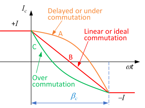
During a Maxwell simulation, armature coil currents are determined from the input armature sweeping current based on linear commutation. However, the assumed linear commutation (see curve B in the following figure) is an ideal case. In real applications, the current shape of the commutating coil depends on the total induced voltage of the coil, which includes inductance- and rotation-induced voltage components. When the inductance-induced voltage is larger than the rotation-induced voltage, the current commutation will lag curve B, as shown by curve A. This case is called delayed or under-commutation. When the rotation-induced voltage is larger than the inductance-induced voltage, the current will commutate as it approaches curve B, as shown by curve C. This case is called over-commutation. The difference between the real and the linear commutation currents is called commutating current.
The commutating current will change the main magnetic field because the axis of the commutating coil aligns with the axis of the main field. As a result, it will affect the values of flux linkages of all coils and the rotor torque. To improve model accuracy, we can include the effect of commutating current on the main field. Therefore, in addition to sweeping the input armature current, we also sweep the commutating current. In this way, we can consider the commutating current effects on the main field. However, the resultant commutating current effect is estimated based on one or two coils rather than the commutating current effects of one coil by one coil, so it is not highly accurate.
Therefore, you can scale the weight of the commutating current effect using the effCom argument. When effCom = 0, the commutating current effects are not considered. When effCom = 1, the commutating current effects are 100% considered.