
Defining the Stator Winding Data for a Switched Reluctance Motor
The stator coils provide the excitation for the rotating magnetic poles.
Use the Stator Coil window to define the parallel branches, wire specifications, and slot liner for the stator coil.
To define the stator coils:
- To open the Stator Slot Winding Properties window, double-click the Machine > Stator > Winding entry in the project tree on the desktop. You can also enter values in the Properties section of the desktop without opening a separate window.
- Enter the thickness of the insulation between the stator core and the field winding in the Insulation Thickness field.
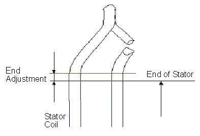
- Enter the end length adjustment of the
stator coils in the End Adjustment
field. The end adjustment is the distance one end of the conductor extends
vertically beyond the end of the stator.
- Select or enter the number of parallel branches in one phase of the winding in the Parallel Branches field.
- Enter the number of turns per stator pole in the Turns per Pole field.
- Enter the number of wires per conductor in the Number of Strands field. Enter 0 to have RMxprt auto-design this value.
-
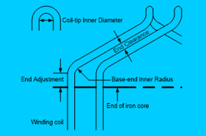
Enter the inner radius of the base corner in the Base Inner Radius field.
-
Enter the inner diameter of the coil tip in the Tip Inner Diameter field.
-
Enter the distance between two stator coils in the End Clearance field.
-
Enter the thickness of the slot liner insulation in the Slot Liner field.
-
Enter the thickness of the wedge insulation in the Wedge Thickness field.
-
Enter the thickness of the insulation layer in the Layer Insulation field.
-
Enter the limited slot fill factor for the wire design in the Limited Fill Factor field. The slot fill factor is the ratio between the cross-sectional area of all conductors in one slot and the entire slot area.
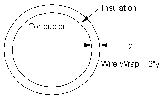
- Enter the thickness of the double-sided
wire wrap in the Wire Wrap field.
Enter 0 to automatically obtain this value from the wire library.
- Select the Wire Size:
- Click the button for Wire Size.
The Wire Size window appears. - Select a value from the Wire Diameter drop-down menu.
- Select a wire gauge from the Gauge
drop-down menu. You can select from the following options:
<number>
You can select a specific gauge number. When you select a gauge number, the Wire Diameter field is automatically updated.
USER
This option allows you to manually enter the Wire Diameter. This is useful when you want to enter a diameter that does not correspond to a particular wire gauge.
AUTO
This option sets the Wire Diameter to zero, and RMxprt automatically calculates the optimal value. The diameter information is then written to the output file when you analyze the design.
MIXED
This option allows you to define a conductor that is made of different size wires. For example, a single conductor may consist of five wires: three wires with a diameter of 0.21 mm and two wires with a diameter of 0.13 mm.
- When you are done setting the wire size, click OK to close the Wire Size window and return to the Properties window.
- Enter the conductor area ratio of the coupled circuit to the main circuit in the Coupled Ratio field.
- Click OK to close the Properties window.
The gauge number is based on AWG settings. You can create your own wire table using Machine > Wire, and then you can select this wire table using Tools > Options > General Options > Machines.