
Editing Wire Data
Users must generate their own data files for wire gauges using data for wire gauge and thickness of insulation provided by manufacturers. There are no national standards for insulation thickness, therefore different manufacturers produce electromagnetic wire with different thickness of insulation. The data file American.wir does not provide data for thickness of insulation; the data file Chinese.wir does provide the data for thickness of insulation, but only for the purpose of reference to users. These files are stored in the file folder syslib along with several other wire data reference libraries.
To define or edit wire data:
- Click Machine > Wire to open the Edit Wire Data
dialog box
- Select the units from the Unit System drop-down menu.
- Optionally, click Import to import wire data from a file. Provide the file name to import in the File name: edit box (or by browsing) and use the default file type Wire Size File (*.wir). Several standard wire libraries are provided in the syslib directory.
- Click the Round or Rectangle tab for the wire shape you want to edit.
- Specify the desired values for Gauge No., Diameter,
and/or Wrap.
Gauge No.
wire gauge index number.
Diameter
diameter of bare copper wire, in mm or inch.
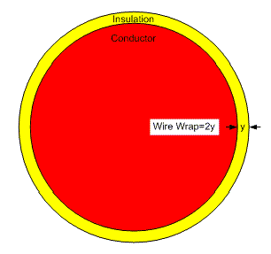
Wrap
thickness of insulation wrap, in mm or inch.
- Modify the wire data as needed.
- Optionally, Add or Delete Rows for wire values.
- Specify the desired values to limit
ratios of the two sides.
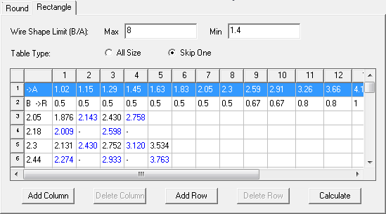
Wire Shape Limit (B/A) max
the maximum ratio between the wide and the narrow sides.
Wire Shape Limit (B/A) min
the minimum ratio between the wide and the narrow sides.
- Use the radio buttons to specify whether to consider priority factors.
- At the intersection of the odd columns and the odd rows, the sectional areas appear in black numbers (recommended to use).
- At the intersection of the odd columns and the even rows or the even columns and the odd rows, the sectional areas appear in blue numbers (rarely used).
- At the cross of the even columns and the even rows, the sectional areas do not show (generally not used).
- Optionally, Add or Delete rows or columns for wire values.
- Optionally, click Export to export the data you entered to a file. Provide the file name to import in the File name: edit box (or by browsing) and use the default file type Wire Size File (*.wir). The default directory for an exported wire data file is userlib.
-
When you are finished, click Save to save the data, and click Close to close the window.
Note: Saving wire data only updates the wire data in the active design.
English Unit System stands for British unit system, Metric Unit System stands for the metric unit system. When changing the unit system, the message box Note pops up to inform changing in unit system is only for specifying input data unit, but not for transferring data between two unit systems
For Round:
For Rectangle:
All Size – for No Consideration of Priority Factors. Select the radio button All Size, and then click the Calculate button. All the sectional areas of wire gauge with the ratio B/A between the wide and the narrow sides satisfying the condition (B/A) max > B / A > (B/A) min appear in the table.
Skip One – for Consideration of Priority Factors. Select the radio button Skip One, and then click the Calculate button. All the sectional areas of wire gauge with the ratio B/A between the wide and the narrow sides satisfying the condition (B/A) max > B / A > (B/A) min appear in three different modes in the table Rectangular Wire Data.
Related Topic