
Defining SALNT_POLE Stator and Rotor Field Winding Data for a Generic Rotating Machine.
- To open the rotor or stator field winding Properties dialog box, double-click the Machine > Stator > Field > Winding or Machine > Rotor > Field > Winding entry in the project tree on the desktop. (You can also enter values in the Properties section of the desktop without opening a separate dialog box.)
- Select a Winding Type:
- Click the button for Winding Type to open the Winding Type window.
- Select Round,
Cylinder, or EdgeWise
winding.
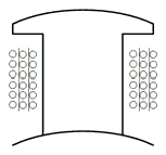
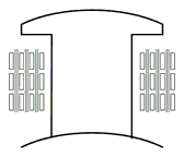
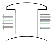
When you place the mouse cursor over a winding button, an outline of the selected winding appears. The following table describes the three types of windings:
Type
Description
Round
A Round winding:
Cylinder
A Cylinder winding:
EdgeWise
An EdgeWise winding:
- Once you have selected a winding, click OK to close the Winding Type dialog box and return to the Properties window.
- Enter the number of parallel branches in one phase of the winding in the Parallel Branches field.
- Enter the total number of conductors for each pole in the Conductors per Pole field. Odd numbers for input and output leads on different sides. Enter 0 to have RMxprt auto-design this value.
- For Round and Cylinder winding types, enter the number of wires per conductor in the Number of Strands field. Enter 0 to have RMxprt auto-design this value.
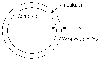
- Enter the thickness of the double-sided wire wrap
in the Wire Wrap field. Enter
0 to automatically obtain this value from the wire library.
- For an EdgeWise winding type, enter the thickness of the inter-turn insulation in the Inter-turn Insulation field.
- Select the Wire Size:
- Click the button for Wire Size to open the Wire Size dialog box.
- Select a value from the Wire Diameter drop-down menu.
- Select a wire gauge from the Gauge
drop-down menu. You can select from the following options:
<number>
You can select a specific gauge number. When you select a gauge number, the Wire Diameter field is automatically updated.
USER
This option allows you to manually enter the Wire Diameter. This is useful when you want to enter a diameter that does not correspond to a particular wire gauge.
AUTO
This option sets the Wire Diameter to zero, and RMxprt automatically calculates the optimal value. The diameter information is then written to the output file when you analyze the design.
MIXED
This option allows you to define a conductor that is made of different size wires. For example, a single conductor may consist of five wires, three wires with a diameter of 0.21 mm and 2 wires with a diameter of 0.13 mm.
The gauge number is based on AWG settings. You can create your own wire table using Machine > Wire, and then you can select this wire table using the Tools > Options > General Options > Machines command.
- When you are done setting the wire size, click OK to close the Wire Size dialog box and return to the Properties dialog box.
- When you are done setting the wire size, click OK to close the Wire Size dialog box and return to the Properties dialog box.
- Click the Conductor Type button to open the Select Definition window Materials tab and selecting the desired conductor material type. Use the Material Filter tab settings to filter for Conductor materials. Click OK to close the window.
- Enter the axial gap between the field winding and pole body in the Axial Clearance field.
- Enter the inner radius at winding fillet in the Winding Fillet field.
- Enter the inner diameter of the coil tip in the Tip Inner Diameter field.
- Enter the limited cross-section width for winding design or arrangement in the Limited Cross Width field. Enter 0 for maximum available area.
- Enter the limited cross-section height for winding design or arrangement in the Limited Cross Height field. Enter 0 for maximum available area.
- Click OK to close the Properties dialog box.