
Commutator Bar and Commutator Bar Model
The commutator bar element is intended to be used for the motor model with a commutator. This element models the variable (periodic) contact resistance between the brush and the commutator bars, as well as the switching (commutation of the current) that occurs when the brush makes contact with the two adjacent commutator bars.
The element itself must always be used together with the corresponding commutator bar model. The commutator bar model can be dropped on the sheet anywhere and needs no connections. Only the commutator bar element itself should be connected as required by the application. The commutator bar elements need to reference the applicable commutator model.
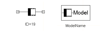
Once the commutator bar element has been dropped on the sheet, you can double-click it to access the properties (make sure the Parameter Values tab is selected). Specify the applicable commutator bar model name in the MOD line and also the Lag parameter in degrees. Lag identifies the angle the commutator bar has to rotate from TIME = 0 in the chosen sense of rotation until it is perfectly aligned with the brush. By default, the element ID and lagging angle in degrees are displayed next to the element.
The commutator bar model needs to be dropped on the circuit sheet. It is unique for every commutator bar element. The commutator bar model contains the following parameters:
- Model name that has to be referenced by all the commutator bar elements;
- R, the full contact resistance between brush and commutator bar, regardless of which of the two is wider;
- WidB is the brush width in mechanical degrees;
- WidC is the commutator bar width in mechanical degrees (does not include the insulation between two adjacent bars);
- Period is the angular periodicity of the positive (or negative) brushes; use 360 for a two pole machine, 180 for a four pole machine with lap winding, etc.