Applying the Commutating Bar Element
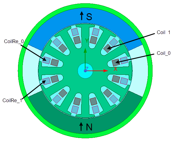
This topic describes how to apply the commutating bar element to simulate the commutating process of brush-type DC machines. A two-pole 12-slot PMDC motor (shown below) is used as an example.
The flux direction inside the S pole permanent magnet is from the air gap to stator yoke, and that of the N pole is from the stator yoke to the air gap.
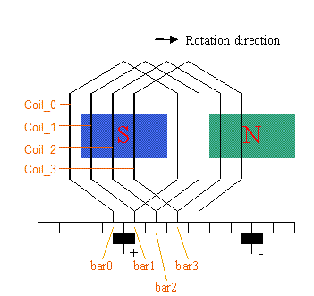
The DC winding is of lap type with coil pitch of 5 slots. The flat-out extensional drawing of the motor indicating the relationship of permanent magnets, coils, commutating bars, and brushes at the initial position is shown below. With the rotation direction shown, the brush aligned with the S pole is positive, and the brush aligned with the N pole is negative. The "go" terminal of Coil_0 connects to bar0, and its return terminal connects to bar1; the "go" terminal of Coil_1 connects to bar1, and its return terminal connects to bar2; and so on.
At the initial time, bar0 lags the positive brush by 15 mechanical degrees (a half commutating bar pitch), and it lags the negative brush by 195 mechanical degrees; bar1 lags the positive brush by -15 mechanical degrees, or 345 degrees, and it lags the negative brush by 165 mechanical degrees; and so on. The functional connection of each commutating bar with the positive brush or negative brush is modeled by BarC (commutating bar) elements, as shown below.
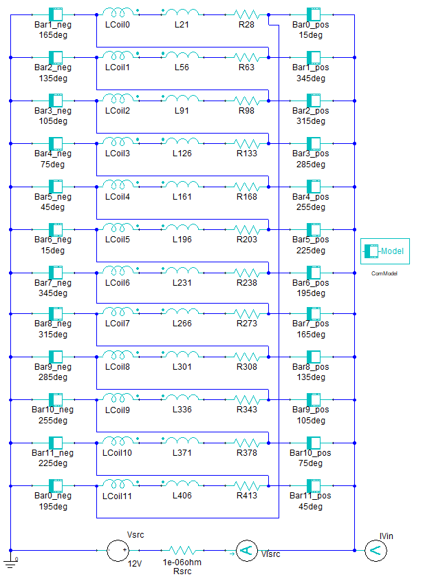
Elements Bar0_pos through Bar11_pos represent the functional connections of bar0 to bar11 with the positive brush, respectively. Elements Bar0_neg through Bar11_neg give the functional connections of bar1 to bar11, and bar0 with the negative brush, respectively. The additional inductor in series with each coil inductance represents the end turn effect that is desirable to consider in a 2D model and possibly also in a 3D model that does not include the end turn geometry. The additional series resistor in series with each coil represents the global resistance of the coil and needs to be included in both 2D and 3D simulations. The values below the BarC element symbols are the respective lagging angles in mechanical degrees. The element parameters can be edited by double-clicking on the element, as shown below.
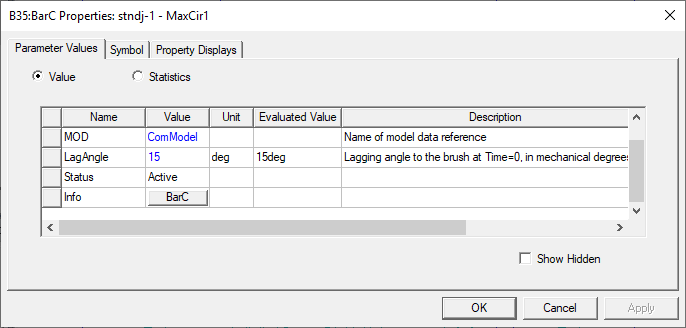
The input value "ComModel" for MOD is the model name that defines the parameters of commutating bars and brushes. The parameters of ComModel can be edited by double-clicking the BarC_Model element.
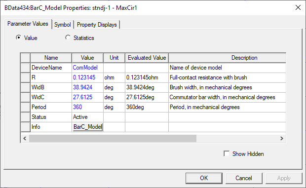
In this design, the commutator diameter is 24 mm, and the brush width is 8 mm. Therefore, the brush width in mechanical degrees is the following:
WidB = 2 * arcsin(8/24) = 38.9 (deg)
The number of commutator bars is 12 (the same as the number of slots), and the commutator insulation thickness is 0.5 mm. Therefore, the commutator bar width in mechanical degrees is the following:
WidC = 360/12 - 2 * arcsin(0.5/24) = 27.6 (deg)
The electric conductance between a commutating bar and a brush varies with the rotor position and can be derived from the model parameters, as shown below, where Gmax = 1 / R.
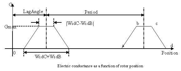
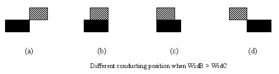
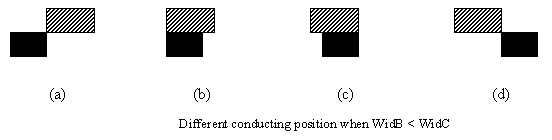
LagAngle is treated as a BarC element parameter because it is different for different commutating bars. All other values (Gmax, WidB, WidC, and Period) can be obtained from BarC_Model parameters. Positions a, b, c, and d correspond to the positions when one side of a commutating bar (solid color) aligns to one side of a brush, as shown below.
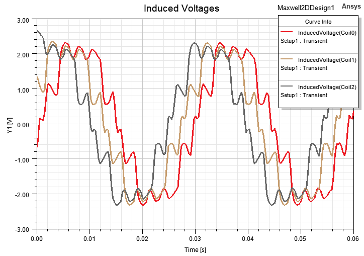
The computed no-load induced voltages for three of the coils, taking into account the commutating process, are shown below.