Automatic Detection of Reaching Steady State for Transient Simulations
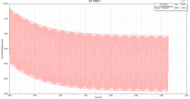
For transient simulations, when the time constant of the design is large, many cycles may be needed to reach steady state.

Because it is often difficult to predict how many cycles are needed to reach the steady state, the user typically must preset a very long simulation time range (a large stop time) to ensure that steady state can be reached before the end of the simulation. This can result in the waste of significant simulation time for cases in which steady state is reached long before the set stop time.
Enabling the Auto Detect setting using a preset Stop Criterion causes the solver to check whether steady state has been reached during the simulation, automatically stopping the simulation when steady state is detected. This allows the user to set a very large stop time without concern for wasting needless simulation time, thus improving the efficiency of the simulation without losing the accuracy of the solutions.
Design Considerations
All windings in a project are divided to three categories: AC winding, DC winding, Non-applicable winding.
-
For an AC winding, the winding source is periodic with the same frequency as the user-set frequency (Frequency of Added Voltage Source) and it has no DC component. A winding which is connected to an external circuit is treated as AC winding.
-
For a DC winding the value of the winding source doesn’t change throughout the simulation.
-
A non-applicable winding is a winding which cannot be included in either of the first two categories, such as the case when the frequency of the source is different from the frequency set by users.
If a project only includes AC windings and DC windings, automatic detection will be conducted by checking the flux linkages of all AC windings. If a project includes a Non-applicable winding, the automatic detection feature will be disabled.
How Auto Detection Works
Winding information is checked during simulation to determine whether steady state has been reached. If rotational motion is included in the project, the torque is also checked.
Of the three winding parameters that can be used to check whether steady state has been reached during the simulation: current, induced voltage, and flux linkage, Auto Detect uses flux linkage for the following reasons:
- Compared with the induced voltage, which is the time derivative of the flux linkage, the flux linkage itself is less sensitive to numerical noise.
- Similarly, current calculations are not as smooth as flux linkage. Also, when the winding excitation is current, the current is not applicable for detecting steady state.
The automatic check for steady state is carried out at the end of each cycle. The cycle time, T is calculated based on the input frequency (Frequency of Added Voltage Source) supplied by the user: T=1/f.
For example, if the check is carried out at time instant tc, the flux linkage values over the last cycle [tc–T, tc] and the second last cycle [tc–2T, tc–T] will be used. The first checkpoint, tc, is at 3T since, in general, the first cycle is unsuitable for checking for steady state – especially when Fast Reach Steady State is enabled (in which case the first cycle is not even a physical result).
The DC component and the fundamental component of the flux linkage of the two cycles are compared to check for steady state. These components are calculated as follows:
DC component:

Fundamental component:

Assuming the DC component of the flux linkage at the last cycle is D1, and the fundamental components are denoted by F1 and F2 at the last and the second last cycle, the following two criteria are implemented to check for steady state:


where the reference value r is calculated by

Coefficient c is the Stop Criterion for reaching steady state and is set by the user on the solver tab for transient solutions and must be greater than 0 but less than 1 (default = 0.005). Thus the smaller the coefficient is, the stricter the stop criterion for reaching steady state is, and the longer it will take to auto detect when steady state is reached.
If rotational motion is involved, after the flux linkage has converged, the solver will further check whether the torque has reached steady state. In steady-state, the torque should be constant with small deviation. Such deviation can come from mesh noise, cogging torque, slot effects, etc. This deviation should be small compared to the rms value of the torque. To check whether the torque has reached steady state, the solver compares the difference of the average torques in the last two cycles. The difference should be smaller than the tolerance value. (The tolerance value is normalized by the rms value of the torque in one cycle.)
The average value of the torque and the rms value of the torque in one cycle are calculated as follows:The average value of the torque:

The rms value of the torque:

The following criterion is implemented in the solver to check for steady state for torque:

As above, c is the user-supplied Stop Criterion.
