Assigning an Impedance Boundary for the Eddy Current Solver
This boundary condition is used to simulate the effect of induced currents in a conductor without explicitly computing them. Since the conductor must be excluded from the model (saving time needed to mesh and solve for currents), assign the impedance boundary condition to an outside edge of the problem region or to an excluded object.
To define an impedance boundary:
- Select the section of the geometry on which you want to apply the boundary condition (typically a face).
- Click Maxwell 3D > Boundaries > Assign > Impedance to open the Impedance Boundary dialog box.
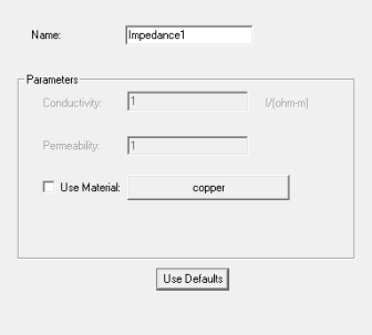
- Enter a name for the boundary in the Name box, or accept the default.
-
Do one of the following:
-
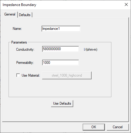
If the Use Material check box is unchecked, enter the conductivity (in inverse ohm-meters) in the Conductivity field, and the conductor's relative permeability in the Permeability field.
-
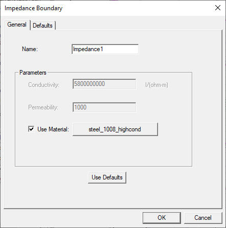
If you wish to select a material from the library, check the Use Material check box, then use the button to select the desired material.
-
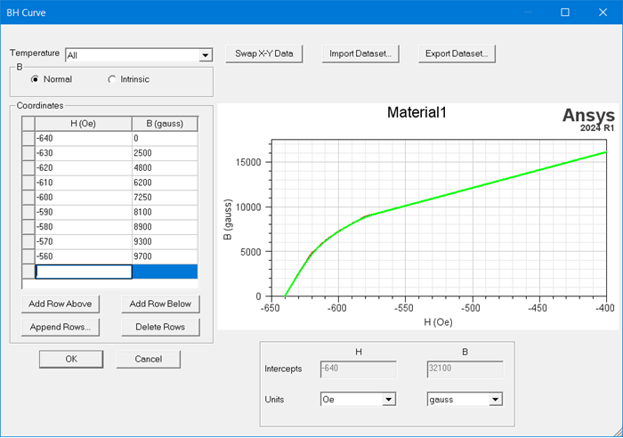
Nonlinear Permeability
If you select a material that has nonlinear permeability, the nonlinear coefficient is computed automatically.
The nonlinear relative permeability of the material is determined by the B-H curve. If the desired B-H curve of the permeability belongs to an existing material, you can directly use that existing material.
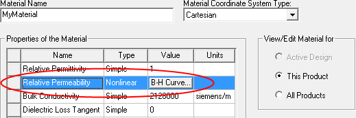
Otherwise, you can edit a new material with the desired B-H curve.
Refer to Relative Permeability for a Maxwell or RMxprt Material for details on using nonlinear relative permeability.
-
Temperature-Dependent Impedance Boundary
The electrical conductivity and permeability of a material used for an impedance boundary condition can be temperature dependent. The Maxwell 3D eddy solver provides an option to allow you to input functions as thermal modifiers to consider the effect of temperature on those properties. To enable this feature, check the Use Material check box as above. You can then click Material to open the material properties panel in which you can add a thermal modifier. (Refer to Setting the Temperature of Objects for additional information on using temperature-dependent impedance boundaries).
-
-
- Optionally, click Use
Defaults to revert to the default values in the window.
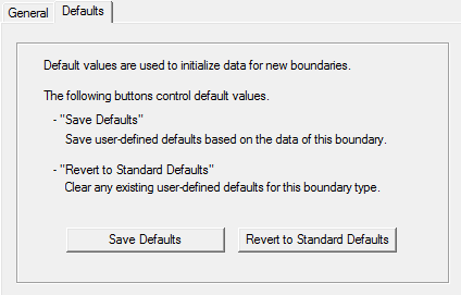
The Defaults tab allows you to control default values. The Save Defaults button saves the values currently defined on the General tab as the defaults to be assigned to new impedance boundaries. Revert to Standard Defaults clears existing user-defined values and replaces them with the standard default values.
-
Click OK to assign the boundary to the selected object.
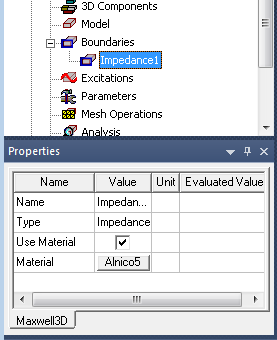
The Project Manager lists the newly assigned impedance boundary in the tree. You can select the boundary in the tree to view and edit its properties in the Properties Window. You can also double-click the boundary entry in the tree to open it for editing in the Impedance Boundary dialog box.