
Assigning a Resistive Sheet Boundary for the 3D Eddy Current Solver
For 3D Magnetostatic designs refer to Assigning a Resistive Sheet Boundary for the 3D Magnetostatic Solver.
When two conductors are in contact within a conduction path, a voltage drop normally exists across the contact surface due to the imperfection of the contact between the two conductors. This boundary condition assigns a resistive sheet to consider the impact of this kind of voltage drop. The resistive sheet is defined by a lumped resistance in ohms.
The following are usages of the resistive sheet boundary:
-
Typical usage: Modeling contact resistance by applying Resistive Sheet boundary to a contacting surface (face) of two conductive objects.
-
Other possible usages: Resistive Sheet boundary can be applied to any sheet object inside a conductive object or on a conductive object surface in order to increase the total resistance of the conducting path and to introduce localized loss density to the place of the sheet location.
This boundary can also be used to model terminal contact resistance (for stranded or solid conductors). For example, by applying it to the conductor cross section touching the region. In this case the Excitation Terminal and Resistive Sheet boundary are not allowed to be on the same sheet object.
The losses incurred due to a Resistive Sheet boundary are output as Surface Loss Density. These losses are counted as losses in solid conductors and are reported together with the losses in other solid conductors under Solid Loss. If the Surface Loss Density is mapped to Mechanical, it should be assigned to a face as Heat Flux.
To define a resistive sheet boundary:
-
Select the section of the geometry on which you want to apply the boundary condition (typically a sheet object or face of a 3D conducting body touching another conducting body or face of a 3D conducting body touching the region).
Note:- The sheet must be completely inside a conductor or on its surface.
- The sheet must have conductors touching both of its faces.
- The resistance value cannot be dependent on intrinsic variable.
- Click Maxwell 3D > Boundaries > Assign > Resistive Sheet to open the Resistive Sheet dialog box.
- Enter a name for the boundary in the Name box, or accept the default.
-
Enter the resistance value in the Resistance field, and select a unit of measure. Use of variables is supported.
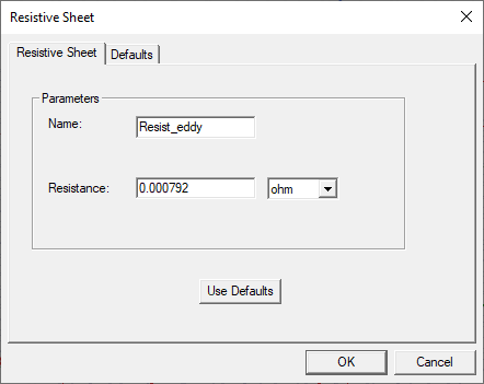
- Optionally, click Use
Defaults to revert to the default value (1 ohm) in the window.
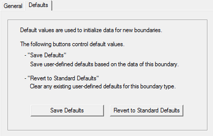
The Defaults tab allows you to control default values. The Save Defaults button saves the values currently defined on the General tab as the defaults to be assigned to new impedance boundaries. Revert to Standard Defaults clears existing user-defined values and replaces them with the standard default values.
-
Click OK to assign the boundary to the selected object.
The Project Manager tree lists the newly assigned resistive sheet boundary in the tree. You can select the boundary in the tree to view and edit its properties in the Properties window. You can also double-click the boundary entry in the tree to open it for editing in the Resistive Sheet dialog box.
Related Topics
Assigning a Resistive Sheet Boundary for the Transient Solver
Assigning a Resistive Sheet Boundary for the 3D Magnetostatic Solver