
Assigning a Resistance Boundary Condition for a 2D DC Conduction Solver
To set a resistance boundary:
- Select the edge of the geometry on which you want to apply the boundary condition.
- Click Maxwell 2D > Boundaries > Assign > Resistance.
The Resistance Boundary dialog box appears. - Enter a name for the boundary in the Name box, or accept the default.
-
Enter the boundary parameters in the Conductivity, Thickness, and Voltage fields, and select the units of measure. Use of variables is supported.
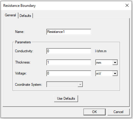
- Optionally, click Use Defaults to revert to the default values in the dialog box.
- Click OK to assign the boundary to the selected object.
Note: Apply resistance boundaries only to the outside edge of the problem space. The external region touching to a resistance boundary is assumed to be a PEC (perfect conductor) with a known potential value that is specified in the resistance boundary setup. Refer to Resistance for technical details.