
Assigning a Cross Section and Dimensions to a Polyline
By viewing the history tree property of a polyline, you can assign either a line, circle or rectangle or isosceles trapezoid cross-section to a polyline. This assignment enables editable dimension properties of width for a line, diameter for a circle, and height and width for a rectangle. To assign a cross-section to a polyline:
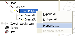
- In the history tree of the Modeler window, right-click on the polyline that you want to give a cross-section.
- In a Properties window (either docked or undocked) for the selected polyline click on None on the Type line under Cross Section to display the choices for Line, Circle, Rectangle or Isosceles Trapezoid.
- Select one of Line, Circle, Rectangle, or Isosceles Trapezoid as the cross-section.
- Selecting Line causes the Cross Section area of the polyline properties to display editable fields for Orientation and Width.
- Selecting Circle causes the Cross Section area of the polyline properties to display an editable field for diameter.
- Selecting Rectangle causes the Cross Section area of the polyline properties to display editable fields for Orientation, Width and Height.
- Selecting Isosceles Trapezoid causes the Cross Section area of the polyline properties to display editable fields for Orientation, Width/Diameter, Top Width and Height.
- If you select Line, Rectangle, or Isosceles Trapezoid, you can edit the Orientation as Auto, X, Y, or Z. This provides the direction in which the dimension extends.
- Specify the dimensions and select the units for the cross-section.
- You can modify the new polyline either by editing the properties, or by using the History tree to select one of the line objects that make up the polyline, and right-clicking to display the drop-down menu showing commands to Insert, Delete, or display editable segment properties.
This selects the polyline, displays the polyline properties in the docked properties (if you have if displays) and displays a shortcut menu where you can choose Properties... to display the undocked Properties window for the polyline.
Type a value in the dimension field(s) and select units from the drop down menu.
The dimensions must be reasonable relative to the specified shape and orientation of the polyline. If the polyline cannot be extended into current Orientation for the given dimension(s), you will receive a warning. If you receive a warning, check the Orientation, dimension and units.
When the modeler can extend the dimensions legally, it displays the modified object, and lists it in the history tree as either a Sheet object (Line or one dimensional Rectangle) or as a Solid object (Circle or two dimensional Rectangle).
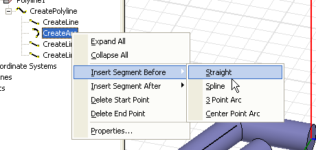
A segment that you select in the history tree is indicated in the Modeler window by a line in the dimensioned object. If you insert a new segment, it adopts the dimensions you specified for the polyline object.
Related Topics
Drawing an Equation-Based Curve