
Analysis Approach for Single-Phase Induction Motors
The construction of a single-phase induction motor is structurally similar to the poly-phase squirrel-cage induction motors. The primary difference is that the stator windings, which consist of a main winding and an auxiliary winding, have axes of these that are displaced 90 electrical degrees in space. To produce a starting torque, the currents in the two windings must be out of phase. Usually a capacitor is connected in series with the auxiliary winding so that the auxiliary winding current is forced to lead the main winding current by about 90 electrical degrees. Two parallel capacitors can also be used: one for starting, and one for running, so that both a starting and running performance are obtained.
An algorithm called symmetric component method is applied to analyze single-phase induction motors (IndM1). Both voltages and currents of the main-phase and auxiliary-phase windings are decomposed to positive- and negative-sequence components. The equivalent circuits for main-phase positive-sequence components, auxiliary-phase positive-sequence components, main-phase negative-sequence components, and auxiliary-phase negative-sequence components are shown in (a), (b), (c), and (d) of Figure 3, respectively.
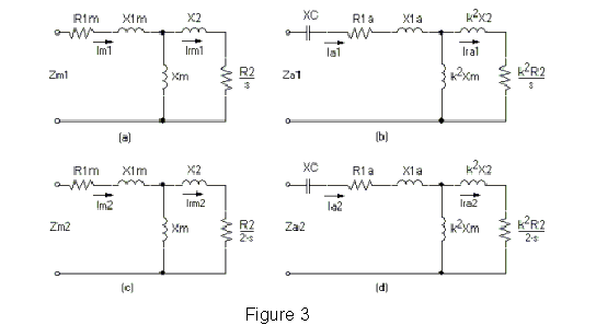
In the figures, R1m, X1m, R1a, X1a, R2, X2, and Xm are main-phase stator resistance, main-phase stator leakage reactance, auxiliary-phase stator resistance, auxiliary-phase stator leakage reactance, rotor resistance, rotor leakage reactance, and magnetizing reactance, respectively. XC is the reactance of the capacitor connected in series with the auxiliary winding, and the coefficient k is the ratio of effective turns of the auxiliary winding to that of the main winding. R2, X2, and Xm have been referred to the main winding. The equivalent impedance of the four circuits is Zm1, Za1, Zm2, and Za2, as shown in the figures.
According to the symmetric component method, the positive and negative components of auxiliary-phase currents can be expressed in the form of a phasor as the following:
Ia1 = (j / k)Im1
Ia2 = (j / k)Im2
Because the main winding and the auxiliary winding have the same applied terminal voltage U1, the voltage equations for both windings become the following:
U1 = Um1 + Um2 = Im1Zm1 + Im2Zm2
U1 = Ua1 + Ua2 = Ia1Za1 + Ia2Za2 = (j / k)(Im1Za1 - Im2Za2)
The positive and negative components of main-phase current are calculated by the following:
Im1 = U1(Za2 - jkZm2) / (Zm1Za2 + Zm2Za1)
Im2 = U1(Za1 + jkZm1) / (Zm1Za2 + Zm2Za1)
The total input current is:
I1 = Im + Ia = (Im1 + Im2) + (Ia1 + Ia2)
Based on these two components of main-phase current, all current components shown in Figure 3 can be obtained by simple computation.
Then the total input current is:
I1 = Im + Ia = (Im1 + Im2) + (Ia1 + Ia2)
The positive- and negative-sequence air-gap power can be computed in the following way:
Pm1 = 2 * Irm1^2 * R2 / s
Pm2 = 2 * Irm2^2 * R2 / (2 - s)
The total air-gap power is:
Pm = Pm1 - Pm2
Tm, T2, P2, P1, and eff are computed in the same way as for three-phase induction motors.
The power factor is derived from:
PF = P1 / (U1 * I1)