
State-Space Characterization
State-space characterization generates linear time-variant reduced order models (LTI ROMs). State-space characterization can significantly reduce the model size and transient simulation time for LTI systems. This approach represents the thermal problem as a system that processes a set of input signals (or simply inputs) yielding a set of output signals (or simply outputs). For a typical thermal problem, the inputs are heat sources at certain locations, and the outputs are temperature rise at specified locations.
When to Use State-Space Characterization
The state-space approach is generally valid for linear systems consisting of forced convection flow and insignificant radiative heat transfer.
Overview of State-Space Characterization
Run a Steady-State Analysis
- Create a steady-state Icepak design.
- After importing or building model geometry, assign thermal boundary conditions that contain parameters to which you'll assign variables the subsequent transient optimetrics analysis.Note:
For the steady-state analysis, ensure the Value is 0 for the parameters to which you intend to assign variables in the transient design.
- Create Temperature monitor points to record the temperature of the boundary condition geometry.
- Analyze the steady-state design.
Run a Transient Optimetrics Analysis
- After the steady-state simulation is finished, copy the steady-state design and paste it in the project.
- Change the Solution Type to Transient.
- Create variables for the boundary condition parameters of interest for the optimetrics analysis.
- Add a solution setup.
- On the General tab, select LTI ROM Defaults from the solutions setup defaults drop-down list.
- On the Solver Settings tab under Import Options, select Start/Continue from a previously solved setup and click Setup Link.
- In the Setup Link dialog box next to Source Design, deselect Use this design and select the steady-state design you previously analyzed and click OK. If the steady-state design solves for flow and temperature, select Frozen flow simulation.
- Click OK in the Icepak Solve Setup dialog box.
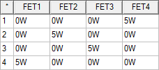
- From Optimetrics, create a parametric setup using all of the variables you've created. Each row in the parametric table should have one variable with the same nonzero value and all other variables with a value of 0. The example below features a nonzero value of 5W.
- Analyze the transient parametric setup.
Use the LTI ROM Parametric Setup toolkit to quickly create a parametric setup for the transient design. See LTI ROM Parametric Setup for more information.
Export LTI ROM
- From the Icepak menu, select Export ROM > LTI ROM.
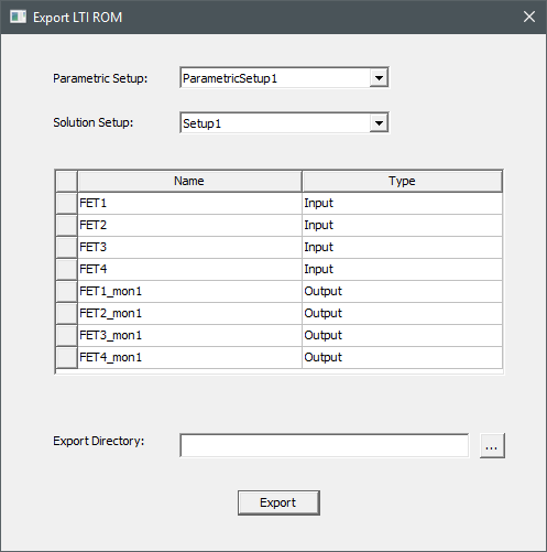
- In the Export LTI ROM dialog box, ensure that the variables are set as inputs and the monitor points as outputs.Note:
If a variable was not used in the setup, select Unused for its Type.
- Select an Export Directory.
- Click Export to generate the files required for TwinBuilder ROM setup.