
Drawing a Bondwire
A bondwire is a thin metal wire that connects a metal signal trace with a chip.
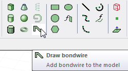
- From the menu bar, click Draw>
 Bondwire or, on the Draw ribbon tab, click the Draw bondwire icon:
- Select the bond pad point in one of the following ways:
- Click the point.
- Type the point's coordinates in the text boxes in the status bar.
- Select the lead point by clicking the point or typing the coordinates in the text boxes in the status bar.
The Bondwires dialog box appears.
- In the Type list, click the modeling standard shape you want the bondwire to have: JEDEC 4-point, JEDEC 5-point, or Low.
The Type selection changes the dialog bondwire graphic, and shows options for that type.
- Enter the number of
The minimum value is 3. The value describes the number of faces that make up the circumference of the bondwire.
- In the diameter field, specify a diameter value and select the units from the drop-down menu.
- Enter the height between the bond pad and the top of the loop in the h1 text box. Include the height's unit of length.
- The value in the h2 text box is the height between the bond pad and the lead point. It was calculated by Ansys Electronics Desktop based on the lead point you selected. If you modify the value of h2, the lead point will be modified.
Optionally, type a new value in the h2 text box. Include the height's unit of length.
- If you selected JEDEC 5-point or Low, do the following:
- Type the angle between the horizontal plane and the wire at the bond pad point in the alpha text box.
- Type the angle between the horizontal plane and the wire at the lead point in the beta text box.
- Click OK.