
Bondwires
A bondwire is a thin metal wire that connects a metal signal trace with a chip. You can choose to draw a standard JEDEC 4-point bondwire, as shown below:
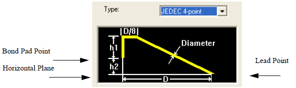
where
h1 = the height between the bond pad point and the top of the loop.
h2 = the height between the lead point and the bond pad point.
diameter = thickness of the wire.
D = the distance between the start and end points, and D/8 is the distance divided by 8.
Or you can choose to draw a JEDEC 5-point or Low bondwire, as shown below:
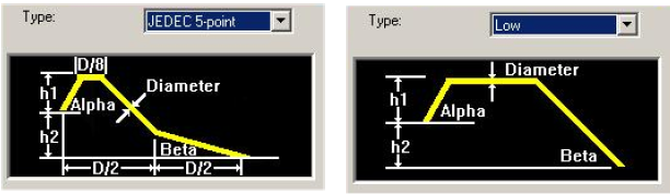
where
a = the angle between the horizontal plane and the wire at the bond pad point.
b = the angle between the horizontal plane and the wire at the lead point.
D = the distance between the start and end points, D/2 is the distance divided by 2, and D/8 is the distance divided by 8.
When drawing the bondwire, you first select the bond pad point, a point in 3D space that defines the bond pad position in a horizontal plane. Then you select the lead point, which indicates the distance the wire covers in the horizontal plane. HFSS will use the distance between the bond pad and lead points to calculate the height between the bond pad and the lead point, or h2, a value that you can modify in the Bondwires dialog box.
For the JEDEC types, notice that the horizontal distance on the wire is calculated as the total length divided by 8. (This horizontal distance is shown in the JEDEC 4 and 5-point figure as "D/8.") For the Low type, the horizontal distance is affected by the Alpha and Beta values as well as the length.