
Design Settings for Icepak
The Icepak>Design Settings command displays the Icepak Design Settings dialog with tabs for Ambient Conditions, Gravity, and Validations. Selecting a current design in the Project tree also displays the Design Settings in Properties window under the solver tab.
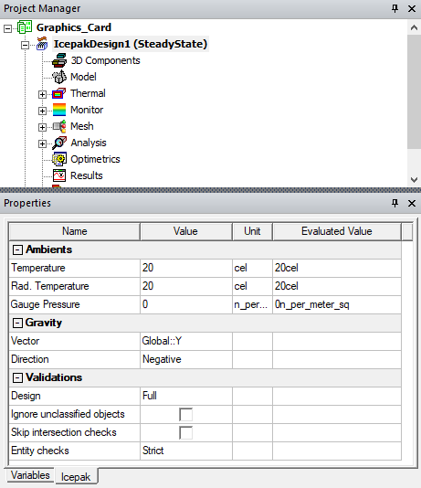
Ambient Conditions Tab
The Ambient Conditions tab allows you to specify the default ambient values for Temperature, Gauge Pressure, and Radiation temperature.

Gravity Tab
When including the effect of gravity for a natural convection simulation, select the appropriate coordinate direction from the Gravity Vector drop-down menu. Also, select Positive or Negative to select in which direction to apply the gravitational acceleration. The gravitational acceleration in Ansys Icepak is 9.80665 m/s2 in the selected coordinate direction.
To include the effect of gravity in the simulation for natural convection models, select Include Gravityin the Icepak Solve Setup Dialog.
The Gravity tab is displayed only when the Solution Type is set as Temperature and Flow.

Validations Tab
The Validation tab offers choices for model validation and Icepak validations to control the extent of validations performed, and therefore the time involved. You can adjust the degree to which the software checks a model for faults that could jeopardize mesh accuracy. There are four levels of model validation that a user can specify for a given design: Warning Only, Basic, Strict, and None. Note that this setting affects only the "3D Model" stage of a design validation. The default Entity Check Level is Strict.
-
The Warning Only entity check setting allows all models to pass 3D Model validation regardless of any faults that are found. These faults are posted in the message window as warnings.
-
The Basic entity check setting allows most models to pass 3D Model validation. Some faults are flagged as model errors, thereby prohibiting a design from proceeding to the meshing stage of an analysis. You must correct such errors before attempting to analyze the design under the Basic setting, or you must change the entity check level to Warning Only.
-
The Strict entity check setting enforces a tighter tolerance for model faults than the Warning Only and Basic settings. All model faults that are found during 3D Model validation are posted to the message window. These errors must be corrected before attempting to analyze the design under the Strict setting, or you must change the entity check level to Basic or Warning Only.
-
The None setting disables model validation.
The following two additional model validation options (check boxes) are available:
- Ignore Unclassified Objects: Generally, all objects in the 3D Modeler's History Tree are classified as solid, sheet, line, or point objects. However, in some cases, a drawing operation may produce null geometry, or it may fail and produce invalid geometry. For example, subtracting a tool object from an equal-volume or smaller blank object completely contained within the tool object would produce a null object. That is, the subtraction would completely remove the original blank object geometry. An example of a failed drawing operation is attempting to unite two solid objects when they only share an edge (not a portion of a face or volume). The union creates a non-manifold, invalid solid body. While not visible in the Modeler window, null and non-manifold objects are listed in the History Tree in an "Unclassified" branch.
- Skip Intersection Checks: Do not check for object interference (that is, overlapping object volumes). In Icepak, you should prioritize objects so that the solver knows which object takes precedence when objects overlap each other.
It is usually best to leave this global modeler validation option cleared so that unclassified objects are not ignored but are flagged as errors.
Design validation settings allow you to choose either:
- Perform full validations (the default setting) – All design validations are performed.
- Perform minimal validations – All design validations except boundary overlap validation are performed.

Export Settings Tab
The Export Settings tab allows you to configure export options for Icepak designs.
Under Export Monitor data, enable Export monitor data after completing simulation to automatically save monitor data in a selected location after the successful completion of a simulation. The data exported includes:
- Solution residuals
- Monitor points
- Network temperatures
By default, the save location is in the project directory. To save the monitor data in different location, select Override and the browse button to open the Choose Directory dialog box.
Under Export data for Sherlock, enable Export temperature data for Sherlock co-simulation to automatically generate temperature data files for use in Ansys Sherlock. By default, the directory "projectname.aedtexport" is created in the project directory (the location where the .aedt project file and folder are saved). The file path is displayed in the Message Manager.
-
Select Solder Fatigue to generate a thermal map (.tmap) file consisting of temperature values for the surface mesh elements on the top and bottom faces of the PCB.
Note:For Solder Fatigue, the design must contain at least one PCB.

Mesh Tab
The Mesh tab allows you to enable meshing options for Icepak designs.
- Select Display mesh after meshing to automatically open the Mesh Viewer and display the mesh after generating a mesh.
- Select Mesh CAD as lightweight geometry to simplify the meshing of imported CAD geometry, thereby reducing the solution time. While matching the solution performance of lightweight geometry, this option retains the full geometry information such that users can make use of the individual CAD faces to assign specific boundary conditions.
- Enable non-isotropic transition for 3D MLM is used to determine how the 3D cut cell mesh generation method subdivides cells near objects. By default, 3D cut cell uses isotropic subdivision which split a hexahedron cell into 8 children hexahedra cells. If Enable non-isotropic transition for 3D MLM is enabled, the subdivision is done anisotropically. The nonisotropic subdivision will create N number of mixed cell types (hexahedra, tetrahedra, prisms and pyramids). The non-isotropic subdivision will lead to a faster meshing time but will contain more cells than an isotropic subdivided mesh.
- Enable temperature secondary gradient for skewed meshes is used to enforce temperature secondary gradient (in advanced solver settings) even in the presence of highly skewed meshes. Temperature secondary gradient might improve accuracy but has a stricter quality requirement on meshes.
- Enable mesh by layer for 2D MLM is used to create 2D multi-level mesh according to different geometry layers.
- Boundary-based mesh refinement is used to insert a layer of prism mesh into Joule heating blocks to improve numerical stability. When user-specified advanced mesh settings are enabled, boundary-based mesh refinement also ensures that there are at least three layers of mesh between heat sink fins.

Advanced Tab
The Advanced tab allows you to enable options to account for the effects of altitude and the Ideal Gas Law.

Altitude Effects
The density variation of air from sea level to higher altitudes can vary considerably. In addition, as the altitude increases, the mass flow rates of fans are reduced.
-
Select Altitude option and specify the altitude and unit. Icepak computes the density of air at a particular altitude based on the International Standard Atmosphere, ISO 2533:1975 published by the International Organization for Standardization (ISO).
-
If a fan or blower is present in the model, enable Update fan and blower curves. This automatically updates the fan characteristic curves based on the ratio of densities of air at the specified altitude and the sea level. Note that this option updates the curves for characteristic curve fans only. Fixed flow fans will have the same constant mass/volume flow at higher altitudes as they do at sea level, albeit with a lower air density.
Ideal Gas Law Effects
Icepak provides options for defining temperature-dependent fluid density. By default, the Boussinesq approximation model is used.
Alternatively, you can enable Ideal Gas Law (see Incompressible Ideal Gas Law), which should be used when pressure variations are small enough that the flow is fully incompressible but you want to use the ideal gas law to express the relationship between density and temperature (for example, for a natural-convection problem). The ideal gas law should not be used to calculate time-dependent natural convection in closed domains.
When using the ideal gas law, also specify the Operating Pressure.
If needed, enable Operating Density and specify the operating density (for ideal gas law or Boussinesq). By default, Icepak will
compute the operating density by averaging over all elements. In some cases, you may obtain
better results if you explicitly specify the operating density instead of having Icepak compute
it for you. For example, if you are solving a natural-convection problem with a pressure boundary,
it is important to understand that the pressure you are specifying is  in Equation 6 under Definition of the Operating Density.
Although you will know the actual pressure
in Equation 6 under Definition of the Operating Density.
Although you will know the actual pressure  , you will need to know the operating density in
order to determine
, you will need to know the operating density in
order to determine  from
from  . Therefore, you should explicitly specify the operating density
rather than use the computed average. The specified value should, however, be representative
of the average value.
. Therefore, you should explicitly specify the operating density
rather than use the computed average. The specified value should, however, be representative
of the average value.

|
Click here for scripting information related to this feature. |